
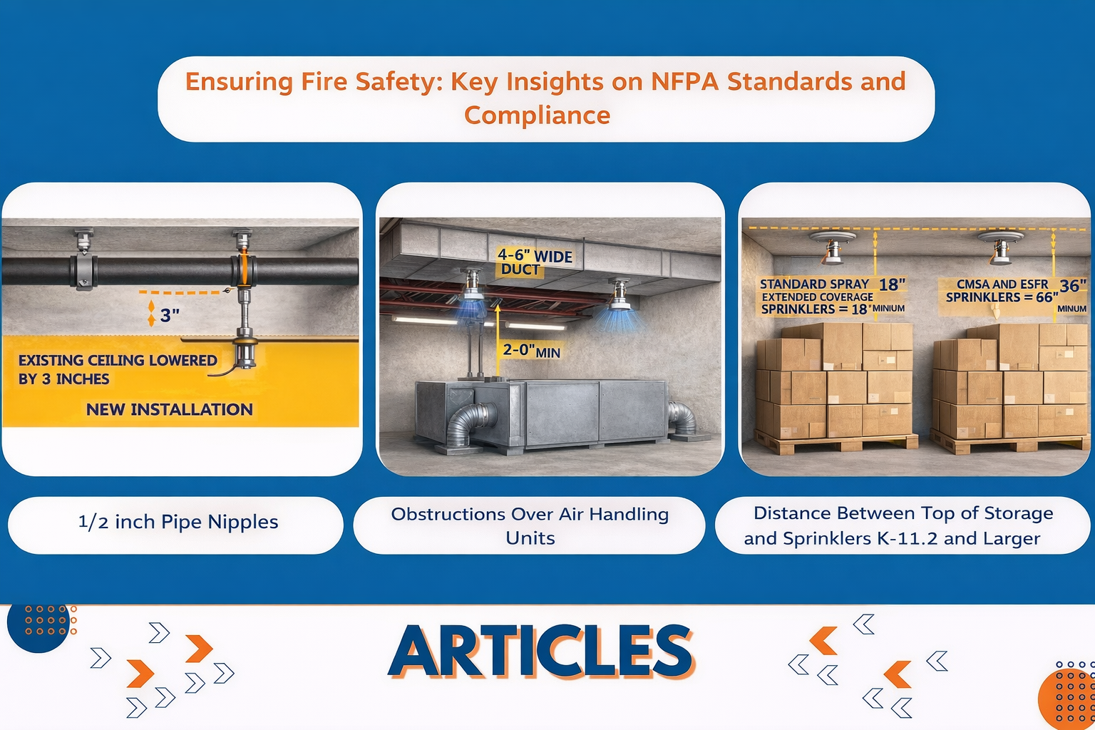
Summary: This article explores common FAQs on NFPA standards’ compliance and fire safety. We investigate several facets of fire sprinkler systems, fire pump operations, and associated safety procedures. Based on the 2010 and 2013 versions of NFPA 13, we provide thorough responses, from the feasibility of reducing suspended sprinklers using particular pipe nipples to the location of quick response sprinklers close to ESFR sprinklers. We clarify the guidelines for inspection tag placement as per NFPA 25 and handle the criteria for sprinkler installation under impediments, such as large ducts over air handling systems.
We also go over the appropriate clearances between sprinkler deflectors and storage piles when utilizing larger K-factor sprinklers and the fit of globe style valves in fire pump discharge piping. Every response guarantees adherence to fire safety procedures and best system performance by offering a thorough knowledge of the particular NFPA recommendations. This blog provides insightful analysis on maintaining and improving fire safety systems regardless of your position—that of building manager, compliance officer, or fire safety professional.
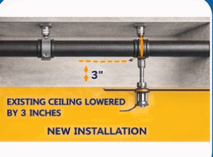
1. 1⁄2 inch Pipe Nipples. Description- Is it possible to use nipples with a 2 inch diameter to lower suspended sprinklers to a maximum of 3 inches without having to open the ceiling to reach the sprinkler drops that are currently in place? This is something to think about for a project where a reduced ceiling will be built. Question 1. One component of a project is building a lowered ceiling that blocks the current pendant sprinklers. Using 1⁄2 inch diameter nipples, is it feasible to reduce the pendants to 3 inches max, avoiding opening the ceiling to access the current drops?
Answer: Yes, there are two ways to “lower” an existing sprinkler, according to the 2016 edition of NFPA 13.
- Extension fittings: The 2016 version has a new definition for this term. These adapters are frequently used to modify how a sprinkler that has been installed in finished walls and ceilings fits in the end. This updated definition complements the addition of new specifications for these fittings in Section 6.4.8. A single extension fitting may be used, provided it satisfies the requirements listed in Section 6.4.8 (multiple extension fittings are not allowed to be linked).
- K-8 or smaller sprinklers are required (6.4.8.1).
- Merely light and common hazard occupancy (6.4.8.2)
- The extension fitting’s internal diameter needs to match the sprinkler’s nominal inlet diameter (6.4.8.3).
- Extension fittings (6.4.84 and 6.4.8.4.1) longer than two inches are to be indicated.
- Extension fittings beyond 2 inches need to be factored into the hydraulic computations.
The extension fitting needs to be specified and taken into account in the hydraulic calculations because the required distance in the scenario as indicated is 3 inches. I haven’t looked into the availability of 3-inch listed extension fittings.
- Revamping: When “revamping” a system, (1) 8.15.20.4 (for pipe schedule systems) and (8.15.20.5) (for hydraulic design systems) permit the use of a 1/2-inch nipple up to a maximum length of 4- inches. This would include lowering a sprinkler to match the height of the ceiling. The following requirements would have to be fulfilled.
- Verification of the required flow rate through calculation. According to the annex (A.8.15.20.5.2), this isn’t meant to be a comprehensive hydraulic analysis.
- Where seismic design is necessary, breasts attached to an armover that have a diameter of less than one inch are not allowed.
-

2. Missing Escutcheon. Description- The 2020 edition of NFPA 25 seems to have a paradox. Section 5.2.1.5 specifies that it must be replaced should the escutcheon for recessed, flush and concealed sprinklers be absent. Section 5.2.1.6 says the escutcheon does not need to be changed if the escutcheon is absent for flush and concealed sprinklers or non-recessional sprinklers. Question 2. Please clarify the several criteria for these two sections.
Answer: The main distinction is Section 5.2.1.5 addresses flush, concealed, and recessed sprinklers. Section 5.2.1.6 covers pendent sprinklers that are not recessed, flush, or concealed.
Many recessed, flush, and concealed sprinklers are tested and listed as an assembly with either their escutcheons or cover plates. These components might be required for the assembly to trap heat to activate the sprinkler; without them, the sprinkler might not turn on as expected and hence the items should be present.
Not deemed a deficiency per NFPA 25, standard escutcheons on pendent sprinklers extending below the ceiling (those not recessed, flush, or concealed) tend not to influence sprinkler activation or performance.
3. Exterior Closets. Description- The outside storage closets of an apartment building following the 2021 International Building Code lack direct access to the units. Question 3. Do these outside closets need to be covered?
Answer: Indeed, NFPA 13 is the design guideline; hence, sprinklers are needed in the exterior closets.
NFPA 13 does not provide an exception for outdoor closets on decks and balconies, unlike NFPA 13R. Every closet must have sprinklers
4. FDC Located upstream of the Main PRV of the Multi-Systems. Description- Six dry systems run under a fire pump safeguard the six-level parking garage. Designed with two shut-off valves on both ends, a main PRV sits upstream of these dry systems to control system pressure at 165 psi. Question 4. Installed above the primary PRV is the FDC. Is this reasonable?
Answer: Although NFPA 13 does not expressly forbid the FDC from connecting upstream of the pressure lowering valve, for a few reasons, this arrangement may not be the best. One of them is the need to rate the check valve’s piping and components upstream (system side) for maximum pump discharge pressure plus pump suction pressure.
Installing the FDC upstream of the PRV also has no actual advantage. One doesn’t worry about the FDC’s pressure. These flows in parallel cause the pressures to not compound; rather, the flow at any given pressure is raised. Therefore, the responding fire fighters will not overpressurize the system as long as the maximum pressure rating of the system is recorded on the FDC signs.
The third reason is the possibility of failure of pressure reduction valves, therefore prohibiting the responding fire brigade from charging the system from the outside. Though NFPA 13 (2013) Section 8.16.1.1.3 forbids shutting off valves between each system and the FDC, the intention is to not install any components that could stop the fire fighters from charging the system.
Although NFPA 13 allows sizing the pump that exceeds the system rated pressure and providing a reduction valve downstream, NFPA 20 actually forbids doing so. Although the installation of the PRV is allowed since it is located downstream of the fire pump discharge isolation valve, care should be taken with a pump with high discharge pressure.
5. Globe Style Valve - Discharge Piping of Fire Pump. Description- Can a fire pump's discharge piping have a globe style valve installed? This subject relates to the compliance and suitability of valve types for systems of fire pumps. Question 5. Can the discharge piping from a fire pump have a globe style valve installed?
Answer: On the fire pump discharge pipes, NFPA 20, 2022 edition does not allow a globe style valve.
Section 4.17.8 specifies a specified indication gate or butterfly valve to be fitted on the side of the pump discharge check valve pertaining to the fire prevention system. This part especially allows a gate or butterfly valve and does not ask for a globe style valve.
Approved indication valves that are not outside screw and yoke (OS&Y) type are allowed since the manual comments on this part state that isolating valves on the discharge side of the fire pump do not affect the operation of the pump.
Although it seems a listed and indicating globe valve might be fitted on the fire pump discharge piping as it would not be expected to influence the pump’s operation, the requirements of the body of the standard clearly stipulate that just listed gates or butterfly valves may be utilized.
You could want to suggest, per Section 1.5, an equivalency method. I’m not sure why the standard would forbid using a listed and indicating globe valve on the fire pump discharge piping. Finding a listed globe valve that indicates, as in my experience most globe valves have a non- Rising stem and are not indicating type valves, could prove challenging. Going back to at least the 1976 edition of NFPA 20, this need seems to be unaltered.
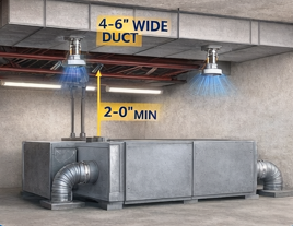
6. Obstructions Over Air Handling Units. Description- Are sprinklers needed under a main duct above the air handling unit, as the linked picture shows? This subject discusses sprinkler system needs and fire safety concerns for spaces blocked by big ducts. Question 6. As illustrated in the attached image, are sprinklers needed below a major duct over the air handling unit?
Answer: “Sprinklers shall be installed under fixed obstructions under 4 feet (1.2 m) wide, such as ducts, decks, open grate flooring, cutting tables, and overhead doors,” reads Section 8.5.5.3.1 (2010 version).
The above suggests that sprinklers should be placed beneath the two ductwork blockages in your design
The language in more recent versions of NFPA 13 clarifies that if barriers larger than 4 feet in width are near the ground, extra coverage is not needed. NFPA 13 (2022 edition) Section 9.5.5.3.1.5 specifies that “Sprinklers shall not be required below noncombustible obstructions over 4 feet (1.2 m) where the bottom of the obstruction is 24 inches (600 mm) or less above the floor or deck.”
This modification was justified by the restricted fuel loads under the obstacle and the difficulty of installing and servicing fire sprinklers given the limited space. That justification allows one to argue to the authority having jurisdiction (AHJ) that the lower duct—two feet above the air handling unit—follows the same logic.
7. Schedule 7 Piping. Description- Plan 7 Piping The goal is to employ Schedule 7 pipe; hence, a third party reviewer is rejecting a submittal package. They have cited Section 16.3.2 of the 2019 edition of NFPA 13 as evidence that the use of Schedule 7 deviates from NFPA criteria. Using Schedule 7 pipe with UL, FM designated for FP, our company's cut sheets indicate they satisfy NFPA 13 criteria. Question 7. What is Section 16.3.2 trying to communicate in obvious terms?
Answer: Schedule 7 pipe is allowed as long as it is especially classified for use in fire sprinkler systems. NFPA 13 (2019) Section 16.3.2 does not apply if the piping being used is correctly listed and installed in line with the listing.
Steel pipe must comply with Section 16.3.1, 16.3.2, 16.3.3, or 16.3.4. Since this is an or statement, only one of the sections applies, not all of them. Pipes listed in Table 7.3.1.1 that do not require listings are covered in Section 16.3.2. The minimum wall thickness required to join the pipe with rolling groove fittings or welding is outlined in Section 7.3.1.1. Since there is no specific listing for the pipe types specified in Table 7.3.1, this section provides basic prescriptive requirements for that installation.
Minimum criteria for threaded pipes are set in Section 16.3.3.
Finally, Section 16.3.4 allows the use of specially mentioned pipe and specifies that the pressure constraints and wall thickness for steel pipe expressly listed in line with Section 7.3.3 should be allowed to be in line with the pipe listing standards. Section 16.3.4 applies, not 16.3.2 since the installed pipe is listed; so, the installation needs to to follow the manufacturer’s guidelines in compliance with the listing.
8. Quick Response Reduction. Description- Can rooms less than 1500 square feet benefit from the rapid response decrease indicated in Section 11.2.3.2.1 of the 2013 NFPA 13? This issue relates to the relevance of particular sprinkler installation recommendations depending on room size. Question 8. In the 2013 edition of NFPA 13, may the quick response reduction of Section 11.2.3.2.1 be used where the room's area is less than 1500 square feet?
Answer: No, with an initial design area of less than 1,500 square feet, the quick reaction design area reduction cannot be utilized.
Section 11.2.3.2 of NFPA 13, 2013 edition is particular to the application of the density area design approach, which requires a minimum design area of 1,500 square feet. Applying Section 11.2.3.2.3 would thus begin with a base design area of 1,500 square feet and apply the quick response sprinkler reduction to that area.
Section 11.2.3.3 offers the specifications for the room design technique, which may be relevant in this situation. Using the room design approach does not allow a rapid response area reduction.
9. NFPA 25 Tag Location. Description- Does NFPA 25 prescribe a certain spot for inspection tag placement? This question discusses NFPA 25 criteria-based labeling requirements for inspected fire prevention equipment. Question 9. Does NFPA 25 specify a particular place to apply the inspection tag?
Answer: NFPA 25 does not have any specifications regarding a particular location for inspection tags. Written records of inspection results and any corrective action taken have requirements. Retaining these records for one year following a consecutive inspection activity (NFPA 25 – 2023 edition – Section 4.3.5) also comes under obligations. NFPA 25 (2023 edition) Section 4.3.1.2 permits electronic techniques for storing inspection, testing, and maintenance records; hence, it is not the aim of NFPA 25 to demand a “tag” or a specified site for posting.
Guideline for tags (where utilized) found in NFPA 25 – Annex G “While NFPA 25 does not mandate system status tagging, it is desirable that a certain level of consistency exist between programs,” notes explanatory comments in NFPA 25.
10. Quick Response Sprinkler Next to ESFR Sprinkler. Description- Is it allowed to install quick response sprinklers next to ESFR sprinklers with the 2010 edition of NFPA 13? This concerns the fit and installation instructions for several kinds of sprinklers in the same location. Question 10. In line with the 2010 edition of NFPA 13, can quick response sprinklers be placed right next to an ESFR sprinkler?
Answer: Sure. The 2010 (or later) versions of NFPA 13 do not forbid installing quick response sprinklers immediately next to an ESFR system.
NFPA 13’s Section 8.4.6.1 calls for a draft curtain separating ESFR sprinklers from standard response sprinklers only. Not normal response sprinklers, quick response sprinklers call for no draft curtain. Between ESFR sprinklers and quick reaction sprinklers, there is no need for draft curtains. Although ESFR sprinklers and quick response sprinklers could have somewhat different RTIs—one might be 40 while the other is 45 for example—there is no reason to be concerned about such minute variations
The draft curtain separating standard response sprinklers from ESFR sprinklers addresses the issue that a fire under the standard response sprinklers will open ESFR sprinklers remotely from the fire prior to opening standard response sprinklers over the fire.
That worry disappears when both of the two different kinds of sprinklers have a quick response. Small differences in RTI would still not allow an ESFR sprinkler remote from the fire to open before the rapid response sprinklers above the fire.
The horizontal distance between the sprinkler and the fire, the vertical distance between the sprinkler and the fire, the distance of the sprinkler below the ceiling, the conductivity between the sprinkler and the water-filled piping, and the size of the fire are among the several factors influencing the time when a sprinkler opens. With all these factors, the minor variation between two distinct kinds of rapid response sprinklers has no bearing.
11. Supervision of Test Valve. Description- Does the fire pump test valve call for supervision? This relates to the safety precautions and monitoring needs for fire pump testing apparatus. Question 11. Should the fire pump test valve require supervision?
Answer: Yes. NFPA 20’s Section 4.18.2 calls for the closed position pump header test valve to be overseen. The easiest way to consider this is if the functioning of the fire prevention system suffers when the normal position of a valve is disturbed. For instance, would the fire protection system be able to satisfy its required demand if water were running through the fire pump test header since that control valve was open (usually it should be closed)?
The answer is generally no. The issues remain the same even if the references address the valves typically in the open state. Water has to reach the area of the system experiencing a fire incident. Should water be directed through one of these other valves during a fire emergency, there could not be enough where it is required. Therefore, it becomes crucial to monitor them in their regular state.
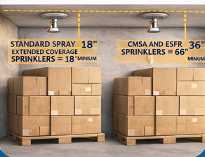
12. Distance Between Top of Storage and Sprinklers K-11.2 and Larger. Description- We are investigating whether using K-11.2 or larger sprinklers necessitates a 36-inch clearance from the top of the solid pile storage to the sprinkler deflector. While 18 inches is the typical clearance, sprinklers such as CMDA, CMSA, and ESFR that have a K-factor of 11.2 or above may require a 36-inch clearance. Question 12. Using K-11.2 or bigger sprinklers, we are looking at if a 36-inch clearance need exists from the top of the storage solid pile and deflector. Although 18 inches is standard, for CMDA, CMSA, and ESFR, greater K factors like 11.2 call for a 36 inch clearance from the top of the storage and deflector.
Answer: Minimum standards for sprinkler deflector distances to top of storage for several kinds of sprinklers are found in NFPA 13 (2022 edition):
- Section 10.2.8.1 calls for Standard Spray Pendent (SSP), Upright (SSU), and Sidewall: 18 inches
- Extended Coverage (EC): Section 11.3.7 – 18 inches
Control Mode Special Application (CMSA): Section 13.2.9, 36 inches
- Section 14.2.12, Early Suppression Fast Response (ESFR), 36 inches
There are also a few other factors:
- The particular sprinkler manufacturer could have different distances from top of storage to deflector.
- Some of the storage design applications (Chapters 20 and 24) specify maximum storage height and maximum ceiling / roof heights (typically, a greater distance from storage to ceiling requires more density); hence, sometimes there is a balance between maintaining the minimum distances but not getting too far away so as to increase the density.
Courtesy: Roland Asp, CET, TechNotes