It is typically around the same time of the year that our maintenance team starts planning to perform annual testing and inspection on fire pumps at clients’ sites. A question that is quite often being raised during this time is what are the minimum code requirements that need to be met during these annual tests and how the results of flow test should be interpreted.
Fire water pumps inspection, testing and maintenance requirements are governed by NFPA 25, Standard for the Inspection, Testing, and Maintenance of Water-Based Fire Protection Systems. As per 2017 Edition, section 8.3.3 of this standard, the annual flow testing of fire pumps should be performed as a minimum at three points across pump curve; no flow (churn), 100% of the pump rated capacity and 150% of the pump rated capacity by controlling discharged water through approved discharge devices. If pump can not be run at 150% of the rated capacity, maximum flow rate under rated speed of the pump should be achieved during the flow test.
For both electric and diesel pumps, the pump suction and discharge pressure and pump RPM should be recorded at any given test point. For electric pumps, pump controller voltage and amperage readings should also be captured at all test points. The voltage and amperage requirements for electric pumps will be covered in the next blog post
As an example, for a pump with a rated capacity of 2000 GPM, test points are 0 GPM, 2000 GPM and 3000 GPM (150% of rated capacity). If 3000 GPM can not be achieved during the flow test, then the maximum flow rate should be targeted, and the maximum flow rate along with corresponding suction and discharge pressures should be recorded.
Once the flow test is completed, results should be interpreted using the pump name plate data and/or manufacturer curve (ideally those two should match but it is not always the case!). If pump differential pressure at any of the test points is less than 95% of the pressures recorded on name plate/manufacturer pump curve for the same test point, then it can be concluded that pump is failing to meet NFPA 25 requirement for annual testing or simply put it is under-performing.
For the example discussed above, If pump name plate data indicates that pump should deliver the rated capacity of 2000 GPM at 160 psi differential pressure, any differential pressure of less than 152 psi recorded at the same flow rate, indicates pump failure in meeting NFPA 25 flow test requirements. To have a visual presentation of the pump performance versus manufacturer curve or name plate data, you can plot both in a same figure (see example below). since pump curves are not linear but second order, choosing the smooth line option for chart type in Excel software rather than the straight line will give you a more accurate graph for performance comparison with manufacturer curve.
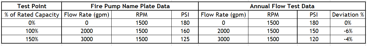
Flow test results in comparison to name plate data – Take note of deviation percentage calculated at the last column
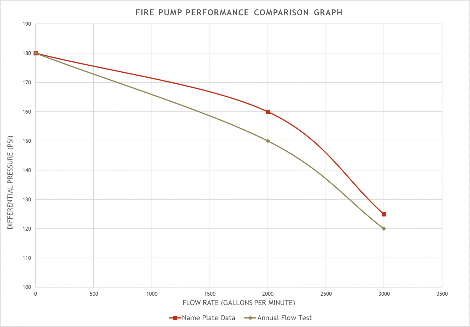
Example of a curve showing pump performance versus reference data (name plate data or manufacturer curve)
One common mistake in conducting flow tests, specifically when the expected flow rates are not achieved, is to increase pump speed beyond the pump rated RPM to achieve the desired flow rate. this is NOT permitted per NFPA 25 as a mean to meet the capacity requirements of the system. If results are obtained at a pump RPM less than the rated RPM, all flow rate and pressure values should be adjusted to reflect on impact of reduced RPM using formulas derived from affinity laws (to be discussed in another post).
Another common mistake is to compare the recorded discharge pressure in gauge with a differential pressure indicated on the pump name plate or manufacturer pump curve. To avoid that, ensure that both pump suction and discharge pressure readings are captured while testing and differential pressure (discharge pressure minus suction pressure) value is used to evaluate pump performance versus with name plate or pump curve data.
Once all test data are analyzed, the flow test report should be submitted to owner for record. If results indicate pump failure in meeting test criteria, following steps should be taken per NFPA 25, 2017, 8.3.7.2.4:
- The owner shall be notified.
- An investigation to find the root cause of the pump degraded performance should be conducted.
- The deficiency shall be corrected.
Over the years, Rotaflow has conducted testing, inspection and maintenance of fire pumps at various sites across Alberta. This vast experience combined with our team’s profound knowledge of Alberta Fire and Building Codes and NFPA Standards provides us with the right set of skills and expertise to take care of your fire system. If you are a facility manager at an industrial site looking for a one-shop solution to all of your fire system needs, contact us to arrange a free consultation.
By: Ali Khakbazan, M.Sc., CFPS, Fire SCO.