

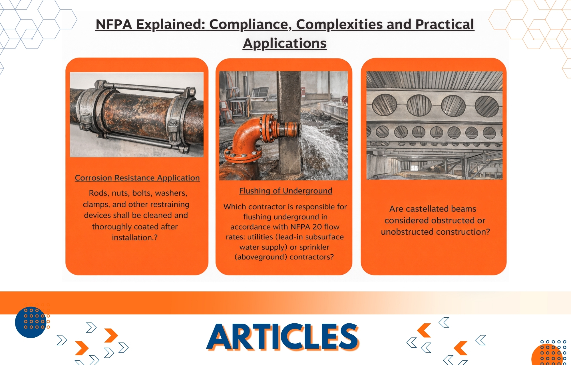
Summary: Here is an in-depth guide to NFPA (National Fire Protection Association) regulations and guidelines for fire protection systems.” This article delves into twelve frequently asked questions, demystifying everything from system installations to structural considerations. Each question delves into specific NFPA standards, offering insight on duties, compliance complexities, and practical applications of fire safety measures.
Negotiate the maze of NFPA standards, from flushing subsurface systems to comprehending the importance of relief valves, selecting proper temperatures for sprinklers, and assessing structural issues like bracing requirements and beam structures. It also provides clarification on dimensions, sprinkler placement guidelines for curved ceilings, fire pump room specs, tank refills, pump installations, corrosion resistance, and other issues. This article is a great resource for fire protection experts and hobbyists, providing clear, succinct explanations and interpretations of NFPA regulations and standards.
#1. Flushing of Underground. Description- The installation of a sprinkler system with a fire pump complies with the NFPA regulations from 2016. A different contractor is installing the aboveground sprinkler system after finishing the subsurface component. The aboveground contractor is asking for the subterranean pipes to be flushed in accordance with NFPA 20 (2016 Edition) Table 14.1.1.1, which is 2,350 gpm for the 8-inch pipe, since a fire pump is being used. The subterranean contractor, however, asserts that the system is installed in accordance with NFPA 24, which calls for 1,560 gpm (2016 Edition, Table 10.10.2.1.3). Question 1. Which contractor is responsible for flushing underground in accordance with NFPA 20 flow rates: utilities (lead-in subsurface water supply) or sprinkler (aboveground) contractors?
Answer: The “installing contractor” is responsible for executing all required acceptance tests, according to Section 10.10.1 of the 2016 version of NFPA 24. Because the purview of NFPA 24 involves private fire service mains, the underground contractor would be the installation contractor in this scenario.
Unfortunately, the 2016 edition of NFPA 24 is unclear on the increased flushing rates required when using a fire pump. According to Section 10.10.2.1.3, the minimum flow rate for flushing must be in compliance with Table 10.10.2.1.3, which in this case is 1,560 gpm. According to the annex to this part, NFPA 20 specifies higher flows for flushing the pipe when the subterranean pipe acts as the suction line for a fire pump.
Because this note is only in the annex, the problem described is all too common. It should be noted that the current version of NFPA 24 (2022) added a new provision (10.10.2.1.3.2) saying that the suction pipe “supplying fire pump(s) shall be flushed prior to connecting to the fire pump(s) in accordance with NFPA 20.”
It is recommended that this issue be brought to the attention of the owner, project engineer, and general contractor to ensure that flushing at the required flow rate (per NFPA 20) is undertaken.

#2. UG Velocity from Storage Tank. Description- The highest velocity allowed is in the pipe connecting an underground storage tank to a wet well, which is powered by a vertical turbine fire pump. Question 2. What is the maximum velocity permitted in a pipe connecting an underground storage tank to a wet well powered by a vertical turbine fire pump?
Answer: The velocity in the approach channel or intake pipe should not exceed about 2 ft/sec, and the velocity in the wet pit should not exceed roughly 1 ft/sec, according to NFPA 20, 2022 edition, Section A.7.2.2.2 for wet pit installations.
#3. Relief Valve on Wet System. Description- Local rules or specialised safety codes, on the other hand, may still necessitate its presence as a preventative step to handle any unforeseen pressure variations, ensure system reliability, and minimise any damage due to overpressure incidents. Question 3. Is it necessary to install relief valves on all wet pipe sprinkler systems even if the usual working pressure does not exceed 175 psi and there is no fire pump or excess pressure pump in the system?
Answer: Yes. Section 7.1.2.1 of the 2013 edition of NFPA 13 mandates that all wet pipe systems have a listed relief valve that is not less than 12 inches in size and is configured to function at 175 psi or 10 psi over the maximum system pressure, whichever is greater. A relief valve is not required when auxiliary air reservoirs are built to absorb pressure increases, according to Section 7.1.2.2.
Temperature changes in a building can cause pressure to rise, and because wet pipe systems are closed systems, static pressure can occasionally approach 175 psi. In reality, many sprinkler components rated for 175 psi have been tested at higher pressures; hence, there have been few known complete sprinkler system component failures when a pressure relief valve is added. However, it is effectively a safety factor (or valve) for the entire system.
#4. Choosing Outside Temperature. Description- What is the best method for determining the proper outside temperature rating for dry pendent sprinklers? This entails determining the temperature at which these sprinklers will activate in reaction to heat from a fire. The technique for determining this temperature often entails taking into account a variety of elements, such as the environment, anticipated fire threats, and relevant safety requirements, to guarantee that the sprinklers respond to fire conditions properly and without false activations or delays. Question 4. What is the best method for selecting the outside temperature for dry pendent sprinklers?
Answer: In previous editions of NFPA 13, an isothermal map of the United States was included to help the designer. It was dropped from the 2022 edition of NFPA 13 for two reasons:
This map was derived from NFPA 24 and was initially meant to determine the burial depth of subterranean plumbing.
The accuracy of the isothermal map has been questioned. Other sources, such as the National Weather Service, were deemed to provide more reliable data for a specific area.
According to NFPA 13 (2022 edition): 16.4.1.1.1 The meteorological temperature used to assess whether an unheated section of a system is at risk of freezing must be the “lowest mean temperature for one day obtained from an approved source.”
While NFPA 13 does not define an approved source (this choice is left to the authority having jurisdiction, or AHJ), NFPA 13R and NFPA 13D do (see Section A.6.7.2.1.2 of the NFPA 13R 2022 edition). This annex note offers the following as reliable sources of historical temperature data:
- National Climatic Data Center of the National Oceanic and Atmospheric Administration • National Weather Service
- Maps of Plant Hardiness Zones (https://planthardiness.ars.usda.gov)
- The American Society of Heating, Refrigeration, and Air-Conditioning Engineers (ASHRAE)
- Other recognized sources
#5. 4-Way Brace on Vertical Pipe. Description- There is a project that has steel columns supporting and bracing an 8-inch horizontal run of main. A 6-inch hose descends down to supply a foam monitor nozzle. A pipe stand at the bottom supports and braces this pipe. The inspector cites Section 9.3.5.8.1, referring to this vertical pipe as a riser, and requires a four-way brace. A qualified structural engineer calculated that the brackets on the columns and the pipe stands are appropriate for support and lateral/longitudinal bracing. Question 5. Is a 4-way brace required at the top of this vertical pipe?
Answer: Yes, according to NFPA 13 (2016) Section 9.3.5.8.1, 4-way braces are required in the places in issue. A riser is defined as “the vertical supply pipes in a sprinkler system” in NFPA 13 Section 3.5.10, which means that any vertical supply pipe is considered a riser.
According to this definition, the vertical pipes in your description and photo are risers.
As stated in Section 9.3.1.2, “Alternative methods of providing earthquake protection of
Sprinkler systems based on a seismic analysis certified by a registered professional engineer such that system performance will be at least equal to that of the building structure under expected seismic forces shall be permitted.”
According to this clause, the professional engineer’s calculations could be utilized to prevent the installation of the four-way brace as long as the documentation is presented to and approved by the AHJ.
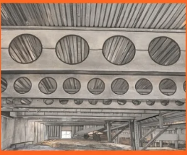
#6. Castellated Beams Description- If castellated beams are used in the construction of a building, there may be concerns or regulations within the standard relating to the installation of sprinkler systems around or within structures utilizing these beams. These provisions would assure optimum sprinkler system coverage and performance in buildings with such structural features. Question 6. Is castellated beam construction considered obstructed or unobstructed?
Answer: A castellated beam is essentially a beam with a recurring pattern of holes.
The size and shape of the holes in the beam (hexagonal, circular, octagonal, diamond, etc.) and/or the spacing of the structural components determine the answer to this issue.
Remember that the cross-section area must be at least 70% open, and the depth of the member must not exceed the smallest dimension of the apertures, or when the beam spacing exceeds 7 1⁄2 feet on center.
Many castellated beams will not meet the 70% open criteria; nevertheless, if the structural elements are spaced 7 1⁄2 feet or more on center, the concept of unobstructed construction will be met.
#7. Listed Head Guards. Description- These NFPA-specified guards are intended to protect sprinklers. To avoid interfering with spray patterns, the National Fire Protection Association requires guards to be ``listed,`` meaning that they have been evaluated to assure minimal impact on sprinkler function. Question 7. Is it required by NFPA 13 to list head guards?
Answer: Yes. According to NFPA 13 Section 16.2.6 (2019 and 2022 editions, Section 6.2.8 in prior versions), sprinklers that are exposed to mechanical injury must be covered with specified guards.
Components are mentioned to ensure that they satisfy the required standard or that they have been tested and confirmed to be suitable for a certain application. Guards, by definition, can interfere with the sprinkler’s intended spray pattern. To verify and reduce the potential impact, the listed guards are tested with certain types of sprinklers.
#8. Sprinklers in a Dome Ceiling. Description- NFPA 13 specifies various methods for measuring distances between sprinklers under a curved ceiling. The distance from the wall to the first sprinkler is measured horizontally along the floor, not along the curved surface. Question 8. When mounted in a dome or curved ceiling, how do you estimate the distance between two sprinklers or from one sprinkler to another?
Answer:
Instead of measuring along the slope of the curved ceiling, the distance under a curved ceiling would be measured horizontally, parallel to the floor. According to NFPA 13, 2013 edition, Section 8.6.3.2.5, the maximum distance a standard spray sprinkler can be from a wall is as follows: under curved surfaces, the horizontal distance measured at floor level from the wall, or the intersection of the curved surface and the floor, to the nearest sprinkler, cannot be greater than half the maximum distance that can be between sprinklers.
The distance between sprinklers is calculated along the slope formed by the two sprinklers under a curved ceiling. This notion is defined in Section 8.5.3.1.2, which states that the maximum distance must be calculated along the slope of the ceiling. According to the manual commentary on this part, for curved ceilings, the distance should be calculated along the slope projected between the two sprinklers, as shown in Exhibit 8.8. The S dimension between sprinklers is shown here, measured along the slope projected from the sprinkler to the neighbouring sprinkler(s).
#9. Fire Pump Room. Description- A sprinkler system, which incorporates a fire pump, protects a warehouse. The pump was supposed to be in a room; however, the room now has only walls and no ceiling. Question 9. Is it required by code for this room to have a ceiling that matches the fire rating of the walls?
Answer: Yes, if the fire pump room is located within the building, it must be rated, which includes a ceiling.
Section 913.1 of the 2018 International Building Code (IBC) requires the fire pump to be located in a room segregated from all other portions of the building by one hour fire barriers.
The fire pump room must also be one hour rated, according to the 2016 edition of NFPA 20, Section 4.13.
In this situation, because the fire pump is housed in a chamber with no rated ceiling and walls that do not extend to the warehouse’s roof deck, the fire pump equipment is not protected from a fire in the building outside the fire pump room. The fire pump room walls would have to extend all the way to the roof deck, or a one-hour rated ceiling would have to be installed.
#10. Underground Water tank refill. Description- A 20,000-gallon subterranean fiberglass fire water storage tank is part of a project. The tank must have an accessible method of filling the tank above grade, according to Section 11.7.3 of the 2018 version of NFPA 22. It makes no mention of an automated refill. Question 10. Is automatic replenishment necessary under Section 14.4.1?
Answer: No, except for “Break Tanks,” as specified in Section 14.5, there is no general need in NFPA 22 for the fill mechanism to be automatic.
Section 14.4 does need a permanent tank fill connection (14.4.1) that is connected to a stable water supply and can fill the tank within 8 hours (4.2.1.4). These provisions state that a permanent fill connection is required but do not specify whether the fill should be automatic.
According to Section 14.4.1.1, the connection is not required if there is no permanent water supply available and there is a plan for manually refilling the tank that is acceptable to the authority having jurisdiction.
It should be noted that the tank must be kept full at all times (14.4.3) and that the NFPA 25 impairment procedures must be followed when the tank’s capacity is insufficient to fulfill the fire protection demand.
There is no particular statement in NFPA 22 that states that an automated fill is not required; nevertheless, there are comments that imply this. 14.4.7, for example, states that “where a separate fill pipe is used, automatic filling shall be permitted.”
Furthermore, the size of the tank may be reduced with the use of a dependable automatic refill. According to Section 4.1.6, the tank should be sized so that the stored supply combined with reliable automatic refills meets the system demand for the required period.
#11. NFPA 13D Pumps Description- The objective is to bring in a single 1-inch feed and split it inside the device. The pump would have to be installed prior to the split and backflow preventers. Question 11. A three-story townhouse will be sprinklered in line with NFPA 13D. For the home water system, a residential booster pump will be provided. Is it possible to utilise the domestic system booster pump for the home sprinkler system?
Answer. Domestic pumps are allowed on NFPA 13D systems. According to Section 6.2, an approved water supply is a link to a dependable waterworks system with or without an automatically operated pump. Because the pump will be linked to the domestic water supply, the conditions mentioned in NFPA 13D Section 6.2.1 will not apply. Domestic booster pumps are likewise not required by the International Residential Code (IRC) (apart from being lead-free).
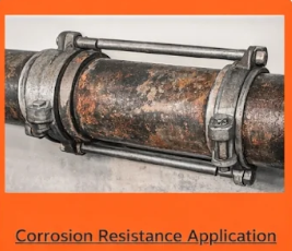
#12. Corrosion Resistance Application. Description- According to Section 10.6.2.5 of the 2016 version of NFPA 24, ``rods, nuts, bolts, washers, clamps, and other restraining devices shall be cleaned and thoroughly coated after installation.`` Question 12 (a). Is this statement true for all metals, including carbon steel, zinc, galvanised steel, stainless steel, and fluoropolymer coatings?
Answer:
The answer is “yes” because this part reads “all” in part 10.6.2.5. The accompanying annex section, on the other hand, clearly specifies steel and iron components and states that “the materials specified in A.10.6.2.5 (1) through (6) do not preclude the use of other materials that also satisfy the requirements of this section.”
So, if the parts used have at least the same corrosion resistance as the steel “components coated with a bituminous or other acceptable corrosion-retarding material,” then this particular requirement does not apply, and there is no need for an extra coating.
Question 12 (b). Does the “after installation” statement imply that all coated materials, regardless of coating type, must still be coated with a bituminous or other suitable corrosion-retarding material?
Ans. No. As previously noted, if the components employed are corrosive,
resistance at least equal to steel “components coated with a bituminous or other coating”
suitable corrosion-retarding material,” this exact rule would not apply, and additional coating would not be required.
Because this clause does not expressly mention this, it is appropriate to consult with the AHJ.
Section 1.4, labeled equivalence, permits the use of a comparable material as long as the substitute material is declared “equivalent” to the standard’s standards.
Courtesy: Roland Asp, CET, TechNote