
Introduction: Fire pumps are crucial components in fire sprinkler systems, providing water flow and pressure to fire sprinklers and standpipes. They are essential for controlling fire spread and preventing flashovers, and are often installed in larger buildings with extensive fire areas. Fire pumps are the costliest and most complicated single piece of equipment in a system, making up the difference between water supply and system demand. They are designed, tested, and listed for fire protection, propelling water through pipes to boost pressure and flow. Centrifugal pumps, a common type, use an impeller to accelerate water into and out of the pump housing.
Pump size is measured in three ways: suction-side (inlet) diameter, discharge-side (outlet) diameter, and impeller diameter. A bigger impeller means more flow and pressure. The hydraulic design of a water-based system is about supply and demand, and if the water supply doesn’t meet system demand, a fire pump may be necessary. System designers evaluate different pumps based on their performance and given water pressure to size them correctly. This delicate balancing act is only one essential component of complex water-based system design.
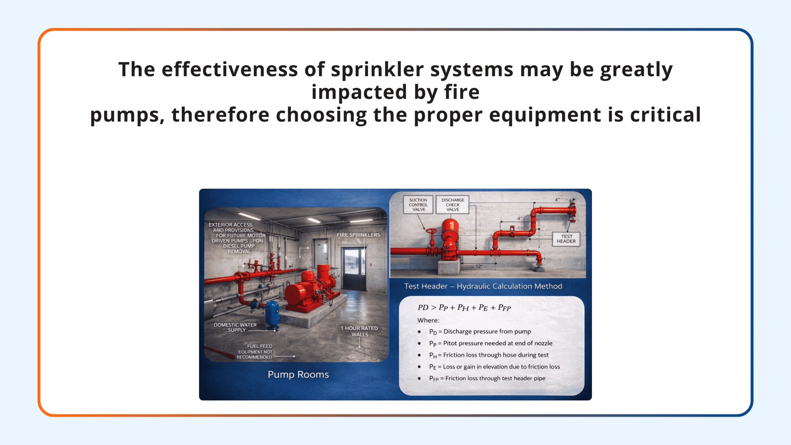
Fire the security of the pump and any associated equipment is of utmost importance since pumps are a vital component of the fire suppression system. A separate pump room has to have enough space for maintenance, appropriate heat, and protection from physical harm and fire. A distant fire pump house is an alternative to a fire pump room, which can and frequently is placed inside the structure it serves. While they are legal, outdoor fire pumps are far less prevalent and will not be covered in this article. The guidelines on equipment protection, including the specifications for the rooms or remote pump houses, are included in Section 4.14 of the NFPA 2022 edition.
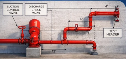
Diesel pump rooms are required to have an automated sprinkler system that complies with NFPA 13 and is made for an additional hazard category 2 occupancy because of the fuel. A pump room with an electric motor-driven pump is not immediately needed to have a sprinkler system, but as was already said, the sprinkler system must extend to the pump room if the building has one. Sprinklers for electric pumps must be supplied, and the system must be built as an ordinary hazard category 1 occupation.
The fire pump chamber should preferably be set aside for that function, however NFPA 20 permits permit the use of equipment for residential water distribution. While home water equipment is allowed, physical damage prevention is crucial. Equipment that can harm a pump in the case of a failure should not be in the pump room because of this. This includes water heaters that use fuel.
- All fire pumps must be flow tested after installation is finished as part of a final acceptance test to show that they can operate at the pressures and flows specified by the manufacturer’s certified curve. All next yearly fire pump flow tests will be compared to the results of this initial field acceptance test. The pressure at churn, or zero flow, the pressure at the rated flow, and the pressure at 150 percent of the rated flow must all be verified by this test.
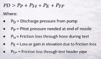
We will utilise the maximum flow from the fire pump or 150% of the rated flow because this estimate must be based on the worst-case friction loss. Additionally, this means that the pump’s discharge pressure will match its rated pressure at 150% of its rated flow.
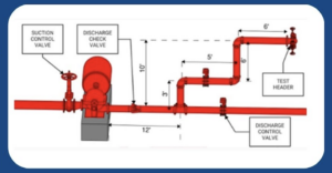
Example of a test header calculation
- Pump Flow Rated: 1000 gpm
- Flow Rate Maximum: 1500 gpm
- Suction Pressure: 1500 gpm at 30 psi.
- At maximum flow, the pump’s net pressure is 58 psi at 1500 gpm.
Unless we surpass 15 feet in length or there are more than four fittings that change the direction of flow after the first connection to the discharge pipe, Table 4.28 specifies that the minimum pipe size for this flow is 6 inches. We will calculate to demonstrate that the 6-inch pipe is appropriate rather than size the pipe larger.
The pipes and fittings between the pump discharge and the test header in our pump configuration are as follows:
- 20 ft. of 6 in. Schedule 40 steel pipe from discharge pipe to test header
- 12 ft. of 6 in. schedule 40 steel pipe from pump discharge to test header line tee
- Fittings
3 elbows (90-degree standard turn)
1 tee
check valve
OS&Y control valve
Height of the pitot gauge is 10 ft. above the pump discharge

We must figure out how much flow is necessary through each hose line as Table 4.28 specifies that the test header must have a minimum of 4 hose valves. By multiplying the maximum flow by 4, we arrive at the need of 375 gpm per hose line. We will further assume that the hoses will culminate in a 1 34 inch straight nozzle with a coefficient of discharge of 0.97.
With this knowledge, we can determine the necessary pressure that the pitot gauge will measure. To achieve this, the pressure component of the formula used to determine the flow from the pitot based on the pressure data may be solved.

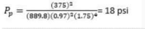
The pitot pressure is computed as follows using the flow from a single flow of 375 gpm, the assuming 1 34 inch nozzle, and the coefficient of discharge of.97:
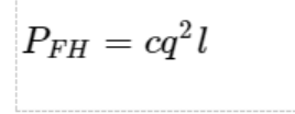
We must make an assumption about the hose type in order to compute the friction loss via the hose. In this case, we’ll suppose that the 100 feet of rubber-lined hose utilised in this test has a friction loss coefficient of 2. The following gives the equation for friction loss through a hose:
The Hazen-Williams formula is used to calculate the friction loss across the supply line going to the test header:
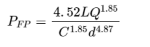
Where:
- L is the total length of the pipe, including the corresponding lengths of the fittings (32 feet plus 107 feet equals 139 feet).
- Q = 1500 gpm maximum flow at pump discharge
- C = pipe C factor (Since a section of this line will be dry, the C factor for steel pipe on a dry pipe system was calculated to be 100.)
- Internal diameter of the pipe (6.65 inches for sch 40 steel pipe)
Therefore,
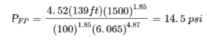
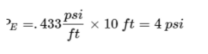
The pressure gain or loss as a result of elevation is the last factor that has to be calculated. We are gaining pressure from the pitot gauge to the pump discharge because it will be 10 feet above the discharge of the pump. Following are the results of multiplying the elevation change by.433 psi/ft to determine this pressure:
We can now compare the values downstream of the discharge to the discharge pressure given all the variables:
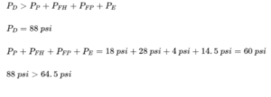
As we have shown, it is appropriate to use a 6-inch schedule 40 steel pipe in this situation. The identical hose types, lengths, and nozzle sizes need to be documented and utilised for all next yearly testing.
Courtesy: NFSA Technotes by Raland Asp,CET in best of NFPA 20.