
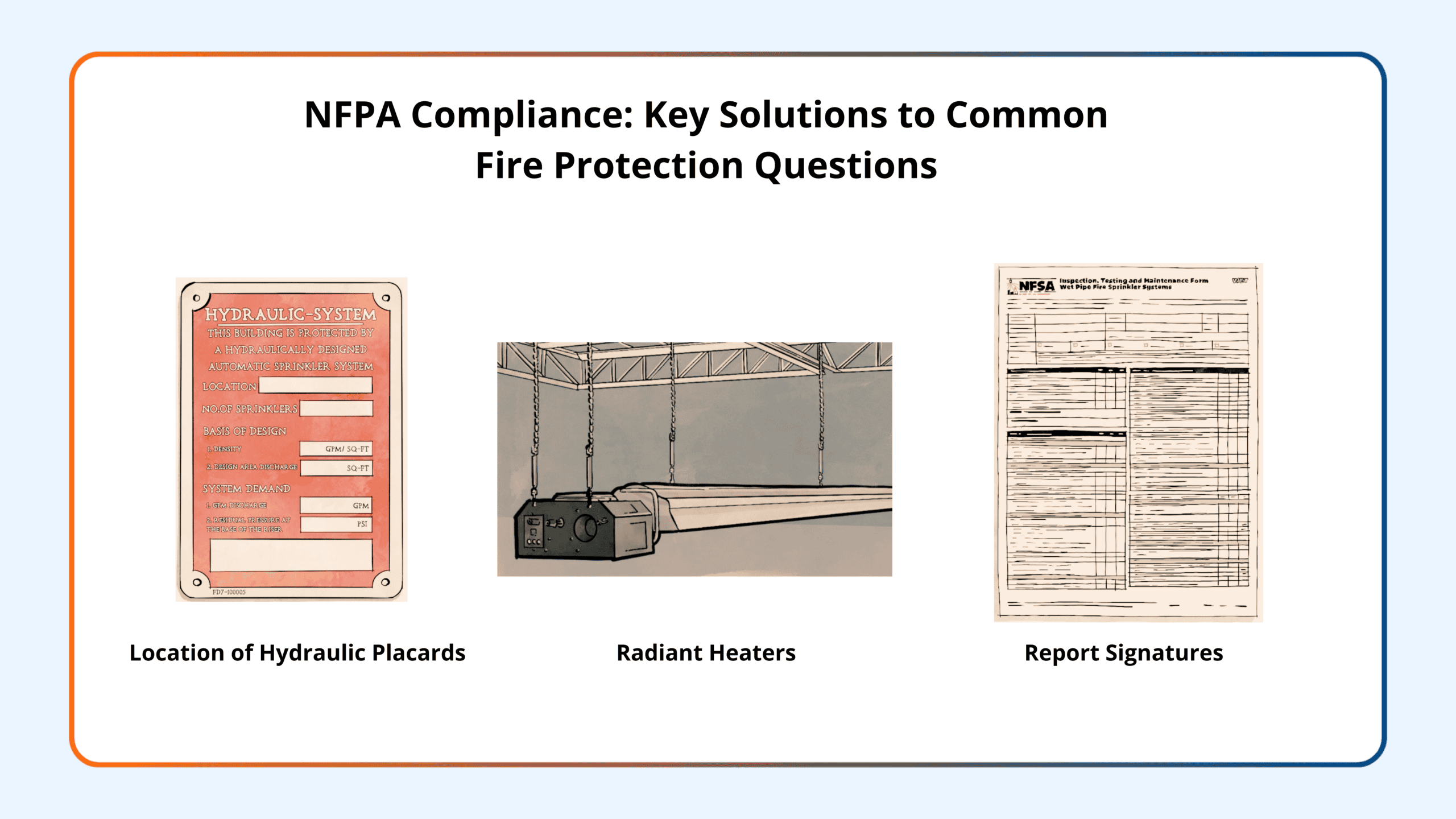
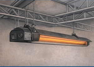
Summary: It is true that the requirements for minimum temperature ratings and separation distances between sprinklers and radiant tube heaters have not changed with the latest editions of NFPA 13. However, it should be noted that the table (Table 9.4.2.5(a) in the 2019 edition of NFPA 13) that addresses sprinkler temperature ratings based on distance from heat sources now includes an entry titled “unit heater and radiant heater.”
This is a minor modification from the 2016 edition, when the article was only labelled “unit heater” and radiant heaters were not discussed. This makes it clear that the same standards are intended to be used by the NFPA 13 committee.
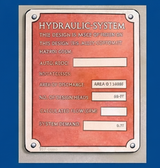
The placement of the hydraulic data indicator varies across NFPA 13 versions, leading to misunderstanding. From 2013 to 2019, the sign has to be placed near the applicable design area’s alarm or dry pipe valve (2013, Section 25.5.1). In the 2022 version, the wording was updated to require the sign to be put at all system risers, floor control assemblies, and alarm valves (2022, Section 29.4.2). The 2022 edition allows the AHJ to advise on sign specifications and exclude new signs. For example, if the water supply, design, and danger are all the same, the AHJ may allow the sign to be removed or duplicated on each level.
Check local codes since they may have more stringent monitoring requirements than norms. In the US, the International Building Code, Section 903.4, takes precedence above NFPA 13, Section 16.9.3.3.1. The IBC does not need a tamper switch. However, if one is installed, it must be an electric switch rather than a chain and lock, as authorised by NFPA 13.
A procedure for downstream of all backflow prevention valves for forward flow testing at a minimum flow rate of the system demand, including hose allowance if necessary, is required by NFPA 13, 2019 edition, Section 16.14.5.1. Section 16.14.5.1.1 specifies that the arrangement described in Section 16.14.5.1 must be serviceable without needing the owner to alter the system for testing.
To test the back-flow preventers forward flow, remove the 6 inch cap and attach hoses. Modifying the system to complete the test does not fulfil Section 16.14.5.1.1’s criteria. To perform the forward flow test, the owner would need to alter the system by removing and replacing the 6-inch cap.
Please note that the 2022 edition has more criteria for this problem. According to Section 16.14.5.1.1, a 2 1/2 inch (65 mm) hose valve should be installed downstream of the backflow prevention valve for every 250 gpm (950 L/min) of system demand, including any appropriate hose allowance. Forward flow tests may be performed using other methods as long as they do not need any adjustments and are appropriate for system requirements.
Fire rules require smoke and heat vents to have at least 360-degree Fahrenheit fusible connections. This permits the sprinkler system to function, and if temperatures rise, vents may open for exhaust.
Section 8.3.2.1 of NFPA 13 (2016 edition) specifies that ordinary and intermediate rated sprinklers must be used throughout a building, not only ordinary or intermediate. It is also permissible to combine ordinary and intermediate temperature sprinklers inside the same compartment. In the 2019 edition of NFPA 13, an annexe note clarifies that it is acceptable to install ordinary-temperature sprinklers, intermediate-temperature sprinklers, or a combination of the two.
Sprinklers in the same compartment may have both ordinary and intermediate temperature, but they must all have the same sensitivity. For instance, sprinklers in a compartment must have either rapid or standard response. The answer types cannot be blended in the same compartment.
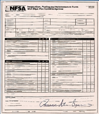
NFPA 25 does not need anyone’s signature. Section 4.3.2 outlines standards for inspection, testing, and maintenance.
- The procedure (inspection, test, or maintenance)
- The organisation doing the task
- The frequency.
- Results and Date.
- The name and contact information for the qualified person(s) carrying out the activity.
Consult with legal counsel to avoid potential pitfalls with contracts, ITM records, and other legal documents.
The travel distance is calculated on the floor or walking surface, following the natural course from the hose connection and allowing for a 12-inch space around corners and barriers.
If the travel distance is excessive, the local Authority Having Jurisdiction (AHJ) may mandate extra hose connections.The International Building Code (IBC) defines a floor as the space inside the inner perimeter of outside walls, and considers balconies to be horizontal projections. However, the standard does not define floor area.
The sprinkler system demand and the available water supply are compared on the water supply graph. There are circumstances in which the demand for the sprinkler system, which includes the pressure generated by the fire pump, is represented by negative pressure figures and does not need a positive pressure from the municipal water supply.
This is typical of warehouse structures. For instance, a warehouse’s design includes a fire pump to satisfy the system’s need for the facility’s storage. However, there is also a light-risk office space. It is feasible that the fire pump may generate much greater pressure on its own without any positive pressure from the municipal water supply if it is sized for both the storage sprinkler system demand and the light hazard office area requirement. In this instance, the needed water pressure from the city would be a negative pressure figure when comparing the system demand to the water supply.
It is true that Section 14.4 mandates a permanent tank fill connection that is linked to a dependable water source (14.4.1) that has the capacity to fill the tank in eight hours (4.2.1.4). These sections do not specify that the fill be automated; instead, they stipulate that a persistent fill connection is necessary.
According to Section 14.4.1.1, if there is a plan for manually replenishing the tank that is approved by the relevant authorities and there is no permanent water supply available, then there is no need for the connection. NFPA 22 merely specifies that the manual fill must be authorised by the AHJ; it offers no instructions on how this should be done. Having the water trucked in to fill the tank is one possibility.
It is important to remember that the tank must always be maintained full (14.4.3) and that in the event that the tank’s capacity is insufficient to fulfil the fire protection requirement (14.4.1.2), the NFPA 25 impairment procedures must be followed.
Although there are several passages in NFPA 22 that suggest otherwise, the document does not explicitly indicate that an automatic fill is not necessary. For instance, the phrase “Where a separate fill pipe is used, automatic filling shall be permitted” appears in Section 14.4.7.
Furthermore, a dependable automated filling system could be able to minimise the tank’s size. According to Section 4.1.6, the tank must be sized so that the system demand is satisfied for the necessary amount of time by the stored supply plus dependable automated replenishment.
The 2017 version was modified to solely mandate flow testing for automated standpipes, including class II. The editions of 2020 and 2023 saw no changes to this.
All manual standpipe systems (except from those that combine manual wet standpipe and automatic sprinkler) and semi-automatic standpipe systems must undergo a hydrostatic test at a minimum of 200 psi, or 50 psi if the typical operating pressure exceeds 150 psi, including the fire department connection. For instance, the hydrostatic test would be necessary at 210 psi for a semi-automated standpipe with a typical operating pressure of 160 psi. Keep in mind that this differs from the acceptance test specifications stipulated in Section 12.6 of NFPA 14, 2024 edition, for new installations.
There are two methods described in NFPA 13 for handling cloud ceilings. First, you must abide by Section 8.15.24. However, it seems from your description that Table 8.15.24.1 is not met by the cloud ceiling. Furthermore, as stipulated in Section 8.15.24.1 (1), the openings need to fulfil requirements 1 and 2. This also doesn’t seem to fulfil Section 8.15.1.2.1.2, which specifies that a gap “longer than 4 feet (1.2 m) shall not have a width greater than 8 inches,” since it has a 12-inch-wide aperture.
The situation in which these clouds don’t fit the requirements in Section 8.15.24 represents the second method for handling them. In this case, you would handle every cloud ceiling panel as if it were a barrier preventing the danger from being reached by the sprinkler discharge. Depending on the kind of sprinkler utilised, the relevant obstruction requirements from Chapter 8 would be applicable. This would mean that each cloud ceiling panel in the scenario would need to have a sprinkler built underneath it since a sprinkler has to be placed beneath any impediment that is wider than four feet.
This is a minor modification from the 2016 edition, when the article was only labelled “unit heater” and radiant heaters were not discussed. This makes it clear that the same standards are intended to be used by the NFPA 13 committee.
Courtesy: Roland Asp, CET, TechNotes