Introduction
Designing a fire prevention system is more than just selecting the proper equipment or installing it in a conventional way. Engineers, contractors, inspectors, and building owners from time to time find themselves in situations where conditions of the project warrant a closer examination of the requirements of the applicable fire protection codes and standards. Questions may be asked regarding sprinkler design, storage arrangements, water sources, fire department connections, fire pumps, system components, and other fire protection features.
This technote collects a number of practical problems that represent some of these typical challenges. Each question tests a particular fire prevention situation and offers insight into how the applicable NFPA standards may be handled. The purpose of this document is to help fire protection experts understand these standards and make good judgements when faced with comparable situations in their projects.
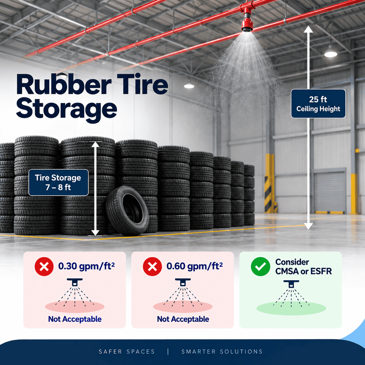
Description: This issue is to clarify the proper CMDA design density for tires placed on their sides on the floor at a storage height of 7-8 feet. It considers the influence of a 25-foot ceiling and the distance between the top of storage and ceiling. The question particularly contrasts a 0.30 gpm/ft² with a 0.60 gpm/ft² design density across 2,500 ft². The answer is needed in accordance with the requirements of NFPA 13, 2016 Edition.
Question 1. What is the appropriate CMDA design density for tires stored on their sides on the floor up to a height of 7 to 8 feet in a building with a 25-foot ceiling? Should the design be based on 0.30 gpm/ft² over 2,500 ft², or should the density be adjusted to 0.60 gpm/ft² over 2,500 ft² because the ceiling is more than 10 feet above the maximum expected storage height? The applicable standard is the 2016 edition of NFPA 13.
Answer: NFPA 13, 2016 edition, Section 18.4 and Table 18.4(a) contain no CMDA design standards for tyre storage on the floor, on their side, with a maximum storage height of 8 feet and a ceiling height of 25 feet.
As previously stated, the sprinkler discharge densities and areas of application are predicated on a maximum clearance to ceiling of 10 feet, with the maximum height of storage expected. The 0.3/2500 square-foot design requirement is not acceptable because the clearance to the ceiling exceeds 10 feet. The 0.6/2500 square feet is unacceptable because the maximum storage height cannot be artificially adjusted to match the ceiling height while maintaining the requisite maximum clearance to storage.
In this situation, you could select a CMSA or ESFR design choice because the same maximum storage height of 10 feet is not necessary as with a CMDA option.
Description: A single-family home is protected by a sprinkler system developed in line with NFPA 13D’s 2019 edition. The garage houses a fuel-fired unit heater, and there is living space above it. Section 8.3.5.1.2 specifies that the AHJ requires a sprinkler above the unit heater.
Question 2. Does Section 8.3.5.1.2 require a sprinkler to be installed over the garage’s unit heater?
Answer: No, sprinklers are not necessary above fuel-fired equipment in a garage, regardless of whether there is living space above it.
Section 8.3.4 indicates that sprinklers are not necessary in garages. The clause makes no exception for the presence of fuel-fired equipment.
Section 8.3.5.1.2 is a subsection of Section 8.3.5 that discusses concealed places like attics and crawl spaces. As a result, its requirements for fuel-fired equipment are limited to such concealed places and do not include garages.
As a result, the presence of fuel-fired equipment in the garage or above the garage does not necessitate the installation of a sprinkler above the unit heater as required by Section 8.3.5.1.2.
Description: I have a question about the requirement for standpipe systems in a structure that is protected by an NFPA 13 sprinkler system. It discusses whether flow from three hose connections should be included in mandatory standpipe demand calculations. The proposed computation is a total standpipe flow of 750 gpm. Is this strategy permitted by the relevant NFPA requirements?
Question 3. A building with an NFPA 13 sprinkler system is also equipped with two standpipes. Is it permissible to add flow from three hose connections when calculating the needed standpipe system demand, yielding a total computed standpipe flow of 750 gpm?
Answer:Yes, such approach is compatible with NFPA 14, Standard for the Installation of Standpipe and Hose Systems, 2019 Edition, Section 7.10, if the riser diagram confirms that the building has two standpipes and is protected by an NFPA 13 sprinkler system.
In a Class I standpipe system, Section 7.10.1.1.1 mandates a minimum flow of 500 gpm through two 2 1⁄2-inch hose connections on the hydraulically most remote standpipe. This demand is calculated at 250 gpm for each hose connection.
Section 7.10.1.1.3 mandates an additional 250 gpm for the second standpipe in buildings with no more than 80,000 ft² per floor. For floor areas over 80,000 ft², an extra standpipe with a flow of 500 gpm is required.
For a structure with two standpipes and a floor area of no more than 80,000 ft², the standpipe demand is:
The hydraulically most remote standpipe delivers 500 gpm, with 250 gpm coming from each of the two hydraulically most remote hose connections.
Second standpipe: 250 gpm.
Total standpipe demand is 750 gpm.
Description: The project includes a fire sprinkler system developed in line with the 2019 edition of NFPA 13. The contractor proposes installing a wet-pipe system in the attic of a three-story structure. The attic walls and roof/ceiling will be insulated with R-38 spray foam, leaving no insulation between the conditioned third floor and the attic. NFPA 13 appears to demand just that the space be consistently kept at 40°F or higher. We haven’t seen this strategy previously and are hesitant to approve it without more supporting material. We propose to need an engineering analysis, including a thermal model, to show that the attic will maintain above 40°F.
Question 4. Is the NFSA aware of such installations? Is there any restriction in NFPA 13 that would otherwise prohibit this arrangement?
Answer: Yes, this arrangement is permitted under NFPA 13. Spray-foam insulation continues to bring more and more attics into the building thermal envelope due to energy-code benefits. NFPA 13, 2019 edition, Section 16.4.1.1 does not prohibit a wet-pipe system in an attic. It requires a dry-pipe or preaction system only if temperatures cannot be maintained at or above 40°F with reasonable certainty. A wet pipe system is permissible if the insulated attic is maintained at 40°F or greater, with the added benefits of lower inspection, testing, and maintenance costs, and the elimination of the hydraulic design-area increase required for dry pipe systems.
But it’s not in compliance to insulate the roof deck and attic walls without insulating the third story ceiling. The third floor heat transfer can help to maintain a steady attic temperature. Its efficiency depends on the building envelope, outside design temperature, air leakage, HVAC operation and temperature distribution within the attic. It is reasonable to request that an engineering analysis or thermal model be supplied that shows that all portions of the attic containing water-filled piping will be maintained at 40°F or higher at all times. Analysis shall incorporate acceptable external design conditions, expected attic temperatures, assumptions about building operation and likely cold spots near eaves, exterior walls, penetrations or roof transitions.
When the analysis fails to establish that the attic will remain at or above 40°F continuously, Section 16.4.1.5 allows water-filled pipes in parts that are at or below 40°F when heat-loss estimations submitted by a professional engineer show the system will not freeze. Otherwise, specify an appropriate freeze-protection method allowed by Sections 16.4.1.2 through 16.4.1.4.2. If the necessary temperature or heat-loss criteria are met, and the spray-foam attic assembly meets the applicable building-code standards, the intended installation is not prohibited by NFPA 13.
Description: This project is a light-hazard use with free and combustible structure. A perimeter beam is located 15 inches from the wall and the sprinkler configuration meets the beam obstruction standards of Table 8.6.5.1.2 in NFPA 13, 2016 edition so that the sprinkler discharge sprays past the beam to the wall. Additional sprinkler in the beam pocket (per Annex Section A.8.5.5.2) is required by the AHJ.”…Where girders, beams or trusses forming narrow pockets of combustible construction along walls can require additional sprinklers of a depth that will obstruct the spray discharge pattern…” We consider Annex information to be informative and not legally binding unless specifically adopted. Therefore, the entire context of A.8.5.5.2 appears to be related to architectural elements.
Question 5. If the sprinkler meets Table 8.6.5.1.2, does Annex Section A.8.5.5.2 justify requiring an extra sprinkler within the beam pocket?
Answer: No, your understanding is correct. Annex notes are not enforced and regardless, as the Beam rule, Table 8.6.5.1.2, is followed, the performance objectives, obstruction criteria, are met.
The Annex remark, A.8.5.5.2, merely affirms this. It says: “Where of a depth that will obstruct the spray discharge pattern, girders, beams, or trusses forming narrow pockets of combustible construction along walls can require additional sprinklers.” However, given this design fits Table 8.6.5.1.2, Beam Rule, this annex comment is silent as the beam rule has established that the beam will not “obstruct the spray discharge pattern” consequently extra sprinklers are not necessary.
This annex note was changed in future edition to make it clear that this note is not concerning architectural characteristics and only reinforces that the obstacle requirements must be met. In the 2025 edition of NFPA 13 this note was changed to A.9.5.5.2 and now reads-
“Where of a depth that will obstruct the spray discharge pattern, girders, beams, or trusses forming narrow pockets of combustible construction along walls can require additional sprinklers. Where the obstruction criteria established by this standard are met, sprinkler spray patterns will not necessarily get water to every square foot of space within a room.”
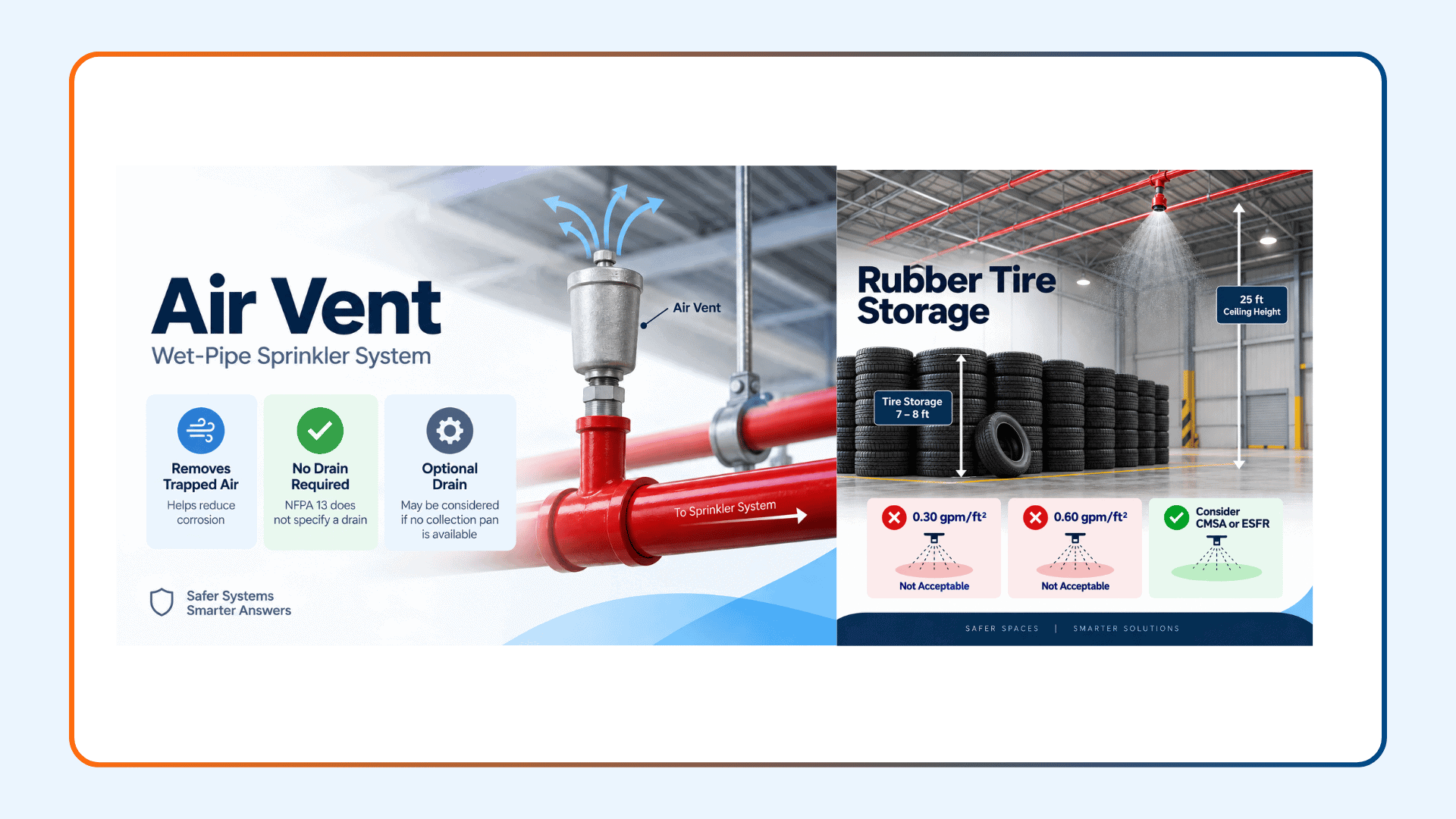
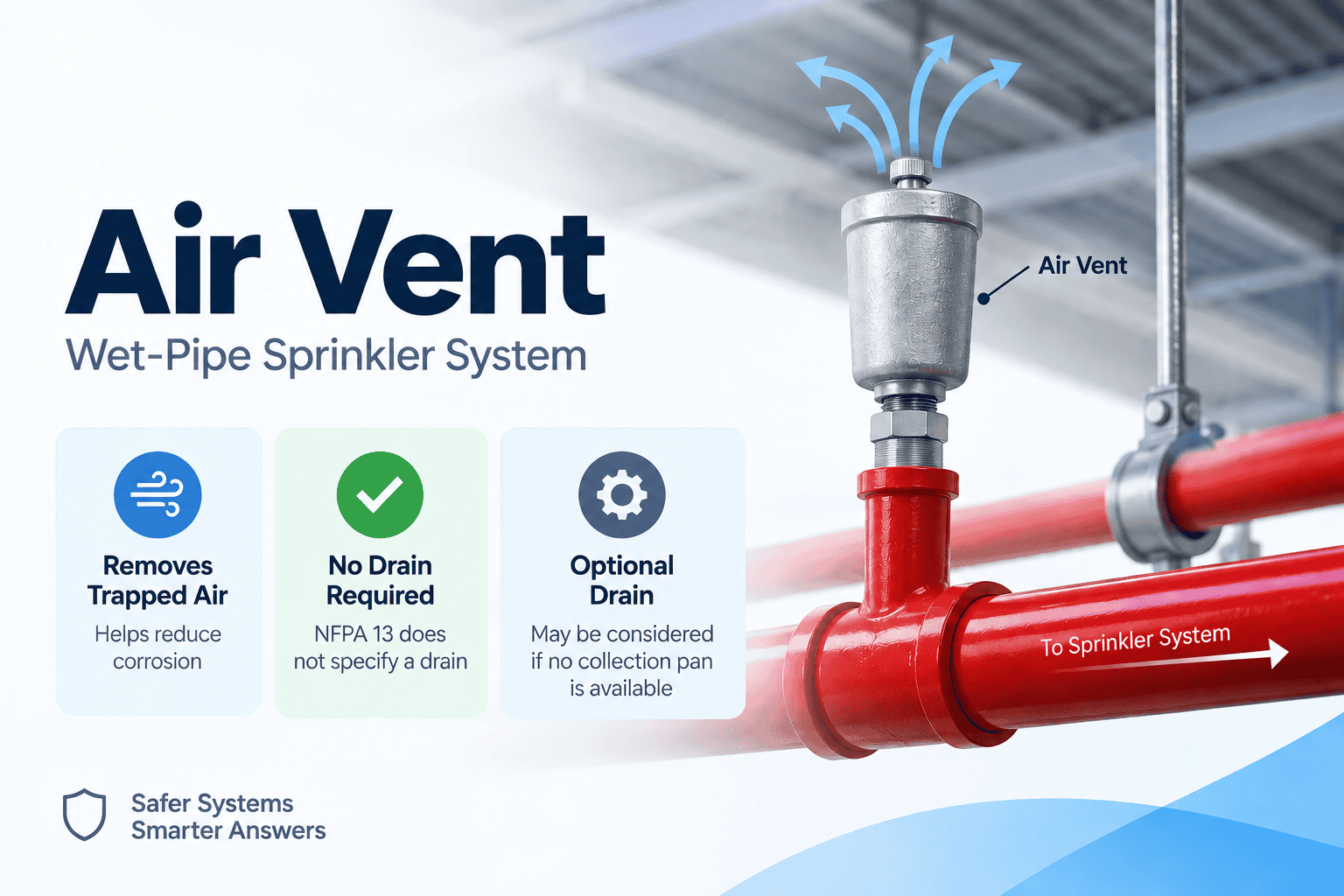
Description: This is a clarification question about air vent requirements for wet-pipe sprinkler systems using metallic pipe per NFPA 13. It concerns the installation of an air vent and if a drainage device is also required to be provided. The question has to do with the practical requirements of draining the air vent. Please advise on the appropriate provisions of NFPA 13.
Question 6. NFPA 13 specifies an air vent for wet-pipe sprinkler systems with metallic pipe. Is it also necessary to provide a method of drainage for the air vent?
Answer: No, NFPA 13 does not specify a drain for the air vent. The vent’s purpose is to evacuate trapped air from the sprinkler system after filling, lowering the risk of corrosion. Some commercially available air vent assemblies incorporate optional drainage features. Because a small amount of water can be discharged after the trapped air is released, a drain connection may be considered in situations where a collection pan is not available or is insufficient to hold the discharge; however, there is no necessity to do so.
Description: This issue is a request for clarification on the number of inlets necessary for a Fire Department Connection (FDC) servicing an ESFR or CMSA sprinkler system. It looks at a system served by a 2,500-gpm fire pump and if two or more FDC inlets would be adequate. It also specifies the required size of supply pipe when the FDC is used as a free standing connection. The question is about FDC inlet and piping requirements for greater demand sprinkler systems.
Question 7. How many inlets are necessary for an FDC serving an ESFR or CMSA sprinkler system? For example, if the system is powered by a 2,500-gpm fire pump, would four or more FDC inlets be necessary, or would two be sufficient?
Also, if the FDC is to be freestanding, will a 4” supply pipe suffice for these higher demand systems?
Answer: With the sprinkler system or fire pump, NFPA 13 requires only two 2½-inch inlets for the fire department connection (FDC). The pipe size serving the FDC shall be at least 4 inches. Standards are provided in section 16.12 of the 2022 edition of NFPA 13.
FDC inlets: Section 16.12.3.1 specifies two 2½-inch connectors on the FDC per section. NFPA 13 does not require an increase in the number of FDC inlets to be provided based on system demand, or the use of ESFR or CMSA sprinklers, or the presence or capacity of a fire pump.
FDC Piping Size: The minimum diameter of the FDC pipes shall be 4 inches per 16.12.2(1). The only time NFPA 13 requires a larger pipe size is when the FDC is intended for use by a fireboat, as described in Section 16.12.2(2). Therefore, if the FDC is distant or freestanding and serves a higher-demand sprinkler system, the pipe to the FDC is 4 inches and is in accordance with minimum specifications of NFPA 13 .
Annex A.16.12.4 explains why two 2½-inch inlets and a 4-inch pipe are sufficient, regardless of sprinkler system demand. “The objective of a fire department connection is to provide additional pressure to an automatic fire sprinkler system. It is not intended to size the fire department connection piping according to system demand.” Unlike an FDC serving a standpipe system under NFPA 14, an FDC serving an NFPA 13 sprinkler system is designed to supplement the available pressure to the sprinkler system rather than supplying the entire calculated system demand. It should be remembered that NFPA 13 specifies minimal requirements. Depending on the project’s individual conditions and needs, the project engineer may decide that additional FDC inlets and/or larger pipework are required.
Description: This subject is related to the application of a single relief valve for numerous wet risers of a sprinkler system. In particular it studies a system with three wet risers connected by a common manifold riser assembly. The issue is whether one relief valve can adequately serve all three risers. Looking for advice on the NFPA regulations that apply to this set up.
Question 8. Can a single relief valve be used for all three wet risers on a manifold riser assembly?
Answer: The relief valve should be downstream of any check valves as per section 7.1.2.3.
Section 4.17.1.1 is new in the 2025 edition. This is from the First Revision No. 72. According to the committee statement, these fittings must be metallic since nonmetallic flexible pump connection connections are prone to failure.
This requirement is intended to relieve any excess pressure in the system that could harm components; most sprinkler components are designated with a maximum operating pressure of 175 psi.
Section 7.1.2.1 Each wet pipe system shall be equipped with a relief valve of not less than 1/2 inch (15 mm) in size set to operate at 175 psi (12 bar) or 10 psi (0.7 bar) above the maximum system pressure, whichever is greater
3.3.23 System. Water supply, control valve, waterflow alarm, and drain as defined in Section
Each riser that comprises a control valve, flow alarm and drain is to be considered a “system” and requires a relief valve, as per Section 7.1.2.1.
Description: This question is to clarify the specifications of a corrugated metal deck in a sprinkler protected structure. In particular, it is the flutes of the metal deck above a draft stop that separates conventional response and ESFR sprinklers. This leads to the question whether the flutes have to be filled up to preserve the intended separation of the spray regions.
Question 9. Is it necessary to fill in the flutes of a corrugated metal deck above a draft stop that divides normal response sprinklers from ESFR sprinklers?
Answer:
No, NFPA 13 does not specify that metal-deck flutes above the draft curtain be filled where the curtain divides an ESFR system from a neighbouring standard-response sprinkler system, as well as an aisle.
A draft curtain, as defined in Section 3.3.63 of NFPA 13, 2025 edition, is a barrier projecting downward from the ceiling that channels, contains, or stops the passage of smoke or heat. Because it is not a fire-resistant separation, NFPA 13 does not require firestopping at all deck flutes.
The annexe to the definition specifies that for more information, refer to NFPA 204. NFPA 204 specifies in the annex that “a draft curtain is intended to be relatively smoke-tight.”
The phrase “relatively” in this sentence introduces several complications. The curtain should be erected to efficiently block heat and smoke. Because NFPA 13 does not expressly address this circumstance, there is undoubtedly some interpretation involved; nonetheless, as previously noted, there is no clear necessity to fill the flutes.
Description: The purpose of this question is to clarify what is required to include packaged fire pump assemblies under NFPA 20. This addresses the question of whether or not the entire packed fire pump assembly must be tested and listed for fire pump duty. The question also goes into whether listing the distinct parts separately would suffice. The goal is to clarify the application of NFPA 20 to packed assemblies as provided for installation.
Question 10. Section 4.31 of NFPA 20 says that “a packaged fire pump assembly, with or without an enclosure, shall be listed for fire pump service.” Is it necessary to evaluate and list the entire packaged fire pump assembly, as given for installation, rather than just the individual components?
Answer: Yes, the standard’s goal is to evaluate and list the entire packaged fire pump assembly, as supplied for installation, rather than just the individual components.
Description: This topic is concerning sprinkler protection for a 5 tier rack storage configuration with solid shelves. It addresses specifically the use of ESFR sprinklers to protect racks with solid shelves. The question is regarding the appropriateness of ESFR protection in relation to the rack arrangement and shelf construction.
Question 11. Is it possible to cover a 5-tier rack with sold shelves using ESFR sprinklers?
Answer: Your inquiry refers to Chapter 23 of the 2019 edition of NFPA 13, which covers early-suppression fast-response (ESFR) sprinklers. ESFR requires highly strict installation criteria, which are frequently based on full-scale fire testing. Sections 23.1.4.1 and 23.6.1.1 specifically state that ESFR are not permitted for solid shelving storage systems.
The exception is ESFR protection with in-rack sprinklers for solid shelves. “Section 25.6.3.4 Where ESFR sprinklers are at ceiling level and protect racks with solid shelving, in-rack sprinklers shall be installed beneath all tiers under the highest solid shelf.”
Description: This is a question about installing sprinkler hangers for mass timber and cross laminated timber (CLT) assemblies with a 2-hour fire-resistance rating. This addresses the issue of whether or not to include the estimated char layer of 3 inches in the design of hanger attachments to the CLT structure. The question is specifically concerned with the need for hanger fasteners to have adequate embedment to extend beyond the projected char depth.
Question 12. This is a question about installing sprinkler hangers for mass timber and cross laminated timber (CLT) assemblies with a 2-hour fire-resistance rating. This addresses the issue of whether or not to include the estimated char layer of 3 inches in the design of hanger attachments to the CLT structure. The question is specifically concerned with the need for hanger fasteners to have adequate embedment to extend beyond the projected char depth.
Answer: NFPA 13 does not mandate that sprinkler-hanger fasteners used in mass timber or CLT extend beyond the projected char layer. The hanger attachment shall comply with applicable NFPA 13 requirements and shall be able to carry the appropriate hanger load on the CLT substrate under normal operating conditions. In actuality, the sprinkler system is designed to go off early and suppress the fire before the CLT experiences the extended fire exposure that would be necessary to produce the expected two-hour char coating.
NFPA 13 specifies a minimum water-supply duration of 30 minutes for light-hazard occupancies and 60 minutes for ordinary-hazard occupancies, which is far before the planned char depth’s two-hour fire-resistance limit. The char layer is used to assess the fire resistance and residual structural capacity of the timber member; it is not an NFPA 13 fastener-embedment criterion. However, the attachment should still be coordinated with the CLT manufacturer and structural engineer to ensure sufficient fastener capacity, appropriate engagement of the CLT laminations, and that the attachment does not jeopardise the rated assembly.
If the hanger connection must sustain the piping for the whole two-hour fire-resistance period, a separate engineered fire-resistance design is necessary rather than merely extending the fastener beyond the nominal char depth.
Closing Thoughts
Fire protection standards often include features that might have a major impact on system design, installation and operation. The questions asked in this technote explain how NFPA regulations may apply based on such elements as storage height, ceiling circumstances, system configuration, equipment selection, and structural characteristics. The technological systems should be developed based on understanding the intent of these provisions, and should comply with the unique conditions of the project.
The questions also emphasise the significance of looking closely at the applicable NFPA provisions rather than assuming or applying a requirement outside of its intended context. Coordination among engineers, contractors, manufacturers, and the authority having jurisdiction in complicated or atypical installations can help guarantee the final design fulfils all applicable requirements and project conditions.