
Summary:
This TechNotes gives clear, practical clarity on frequently asked fire prevention topics about NFPA 13, NFPA 24, and NFPA 25. This resource is intended for engineers, contractors, inspectors, and facility owners. It tackles real-world circumstances that frequently cause misunderstanding during the design, installation, testing, and maintenance of water-based fire protection systems.
The blog covers a wide range of subjects, including correct sprinkler piping support when fireproofing is present, the importance of running several fire pumps during annual testing, and acceptable tolerances for sprinkler deflector alignments. It also defines code purposes for combined fire and domestic water service lines, auxiliary drains for dry systems, and skylights as smooth flat ceilings for sidewall sprinkler installation.
Additional information is provided on how to handle abandoned underground fire protection piping, internal inspection requirements for backflow prevention assemblies, and how NFPA 25 defines deficiencies and impairments when inspection, testing, and maintenance obligations are not satisfied. The blog also looks at important design factors including establishing the usable water level for fire pumps and correctly calculating systems that employ dry sprinklers on wet pipes.
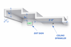
Finally, TechNotes 575 discusses outdoor balcony sprinkler protection where barriers such as support beams are present, assisting professionals in interpreting coverage standards that extend beyond the building footprint.
Overall, this blog serves as a useful resource for bridging the gap between code language and field application, promoting code-compliant decision-making and consistent fire protection performance.
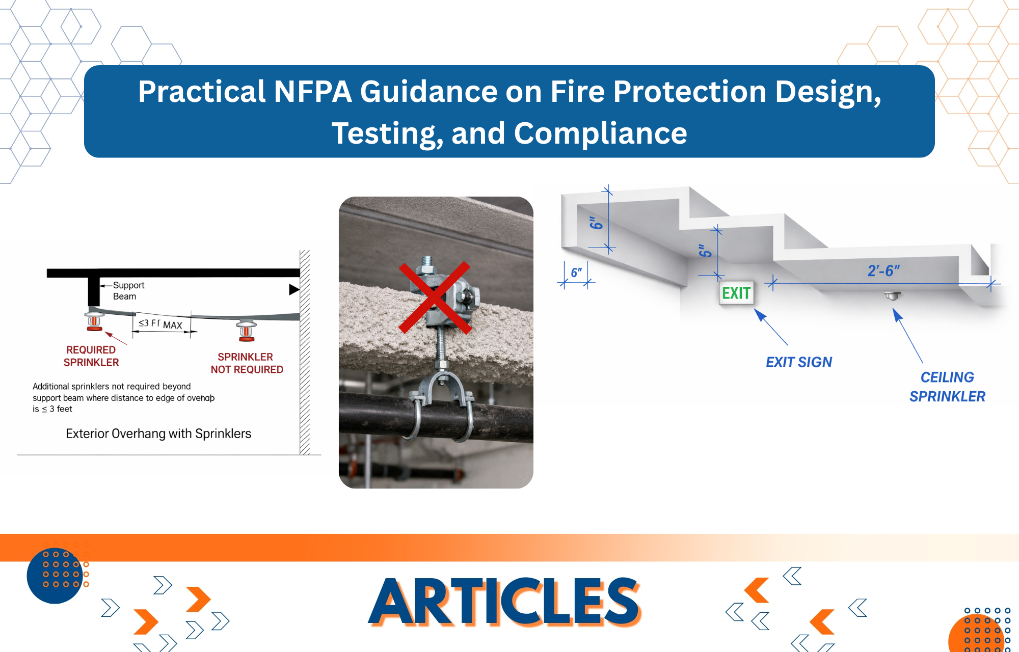
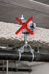
Question #1 – Beam Clamps on Top of Fireproofing
A project’s beams have been coated with fireproofing.
Question #1. Is it permissible to put a beam clamp above the fireproofing?
Answer: No, a beam clamp cannot be set on top of fireproofing because this would prevent a direct connection to the building’s structural steel.
NFPA 13, 2016 edition, Section 9.2.1.3, requires sprinkler piping to be substantially supported from the building structure, which must be capable of supporting the added load of the water-filled pipe plus a minimum of 250 lbs. applied at the point of hanging, unless otherwise permitted by Sections 9.2.1.1.2, 9.2.1.3.3, and 9.2.1.4.1.
NFPA 13 also mandates that components of hanger assemblies that are physically attached to the building structure be specified, unless a particular exception exists. While the standard does not specifically address the installation of beam clamps above fireproofing, numerous critical issues do apply.
NFPA 13 is intended to ensure that hangers and their attachments offer dependable, long-term support for sprinkler pipe. Installing a beam clamp above fireproofing creates uncertainty since the fireproofing material may compress, crack, or decay with time, potentially jeopardising the hanger assembly’s integrity and load-carrying capacity.
Review the manufacturer’s installation instructions for both the beam clamp and the fireproofing material. Many mentioned hanger attachments have been tested and approved for direct attachment to structural steel, not for installation over fireproofing.
If the fireproofing at the attachment point is not removed, the connection may fail to meet the listing criteria of NFPA 13, Section 9.1.1.4.1, 2002 edition and later, which says that “the components of hanger assemblies that directly attach to the pipe or to the building structure shall be listed.”
When attaching to a fireproofed beam, it is normally advisable to remove the fireproofing at the place of attachment to ensure a firm, listed connection to the structural steel. This often necessitates installing the beam clamp before applying the fireproofing, or patching the fireproofing after installing the hanger.
To summarise, installing a beam clamp directly on top of fireproofing is not advised and may not meet the NFPA 13 requirements for listed hanger attachments. Fireproofing is often removed at the attachment site to ensure a secure, code-compliant connection.
Question #2 –Fire Pump Testing – Multiple Pumps
This question asks whether, during annual fire pump testing, more than one fire pump must be run at the same time in order to accurately represent the real system demand that the fire protection system is designed to withstand. It focusses on understanding testing needs in relation to real-world operational settings, rather than on the technique or outcome itself.
Question #2. Is it necessary to operate multiple fire pumps simultaneously during annual testing for system demands that necessitate it?
Answer: Yes, Section 8.3.3.11 of the 2023 edition of NFPA 25 states that where simultaneous operation of multiple pumps is required to meet the water-based system demand for flow and pressure, the testing requirements (churn, flow, and 150%) must be repeated at each flow condition with all pumps operating concurrently.
This was introduced in the 2023 edition, however it has been a requirement of NFPA 20 acceptance testing for several cycles. It appears to have been overlooked in NFPA 25.
Essentially, each fire pump must be evaluated separately before testing the entire system.
Question #3 – Deflector Alignment
A general contractor has expressed concern that the ESFR pendent sprinkler deflectors in an overhead system are slightly out of level with the ceiling.
Question #3. We couldn’t discover a code provision that required the deflector to be absolutely level or specified an acceptable tolerance. Please indicate if a variance of <5° is an acceptable deflector orientation.
Answer: NFPA 13 and NFPA 25 both require sprinkler deflectors to be placed parallel to the ceiling or roof, although neither standard specifies a numerical tolerance for deviation. However, industry practice establishes a defined reference point for what constitutes an acceptable range.
According to NFPA 13, ceilings having a slope of 2 in 12 or less, which translates to around 9.5 degrees, can be classified as horizontal. In such circumstances, sprinkler deflectors can be put horizontally, even if the ceiling is slightly sloped. This effectively means that a deflector can deviate from parallel to the floor by up to 9.5 degrees while still being regarded in compliance. In other words, this 9.5-degree range is the feasible tolerance for alignment when interpreting “parallel to the ceiling or roof.”
While this reference is based on the requirements for upright and pendant spray sprinklers, the same principle is generally accepted across the industry for other standard spray sprinklers, including ESFR, unless the manufacturer’s listing or installation instructions state otherwise; consult the cut sheets. As a result, the 2 in 12 slope allowance in NFPA 13 offers a clear, logical foundation for accepting minor deviations, such as those less than 5 degrees, as compliant and within normal installation tolerances.
Question #4 – Combination Fire/Domestic Water Line
A water service that provides domestic water, a fire sprinkler system and a private fire hydrant, also known as a combination service line, contains a water meter and a backflow preventer installed at the tap off in the City utility easement.
Question #4. Is this combined service line subject to the International Plumbing Code (IPC) or NFPA 24?
Are flushing and hydrostatic testing required, and must the components be identified for fire protection?
Who can install the system—a master plumber or a handyman? And who inspects the line, and to what standards?
Answer: A water service piping system that provides both household water and fire protection, including fire sprinklers and private hydrants, must adhere to both the International Plumbing Code (IPC) and NFPA 24, as adopted and enforced by the International Fire Code (IFC).
The domestic section of the system must adhere to IPC Chapter 6, which includes regulations for water service piping, NSF/ANSI 61 certification, and any flushing, disinfection, or testing required by the IPC or local health and water authorities. Where the service is coupled with fire protection systems, NFPA 24 applies in accordance with IFC Section 507, and items must be compliant with both codes. IPC Table 605.3 and NFPA 24 Tables 10.1.1.1 and 10.2.1.1 specify similar approved subterranean piping materials, such as ductile iron, PVC pressure pipe, polyethylene (PE) pressure pipe, copper tube or pipe, and austenitic stainless steel. Because the combination service provides fire protection, NFPA 24 installation and acceptance testing requirements, such as flushing, hydrostatic pressure testing, operational testing, and forward-flow testing, apply, even though similar testing is not typically required for domestic water services.
Following installation, the fire sprinkler and private hydrant systems connected to the combination service line must meet the inspection, testing, and maintenance requirements of NFPA 25. Where code requirements overlap, the more stringent provisions apply. When materials meet the NFPA 24 requirements, there is no need to specify them particularly for fire protection.
Installation must be completed by properly licensed or registered contractors in compliance with state and local legislation. While not all IPC-regulated work requires professional plumbers, fire service mains are normally installed by fire protection contractors who are registered with the appropriate authority. Plumbing and fire code officials conduct inspections, enforcing the rules in their respective areas.
Question #5 Auxiliary Drains for Dry Pipe Systems and Preaction Systems
This inquiry asks if there are any code or standard requirements that prevent a 2-inch × 12-inch condensate nipple (drum drip) from being manufactured utilising Schedule 10 or Schedule 40 pipe with grooved ends instead of threaded components. It simply questions whether the threaded configuration provided in the standard’s picture is obligatory or merely illustrative.
Question #5. Is there a code/standard constraint that prevents the 2-inch x 12-inch condensate nipple, drum drips, from being manufactured on schedule 10/40 pipe with grooved ends?
The drum drip figure in the standard indicates threaded components.
Answer: In dry systems, there is no clear code restriction in NFPA 13 prohibiting the use of schedule 10 or schedule 40 tubing with grooved ends to produce drum drips or auxiliary drains. The standard focusses on the function and accessibility of the auxiliary drain, rather than the exact method of attaching the pipe, threaded vs. grooved.
In summary, NFPA 13’s recommendation focusses on the purpose and placement of the drum drip and auxiliary drain, rather than the joining method or pipe schedule. Furthermore, the standard does not need threaded fittings in auxiliary drains. Grooved-end pipe and fittings are commonly used in fire protection systems and are authorised as long as they are rated for fire protection and installed in accordance with manufacturer instructions and applicable standards.
Question #6 – Sidewall Sprinklers and Skylights
This topic asks if a ceiling with a skylight and 4-inch-deep mullions can still be categorised as a “smooth flat ceiling” under NFPA 13 (2022), Section 3.3.28.4, allowing the use of sidewall sprinklers permitted under Section 10.3.2(3).
Question #6. According to the 2022 edition of NFPA 13, Section 10.3.2 (3), sidewall sprinklers must be installed below smooth flat ceilings. Please ensure that a skylight with 4-inch-deep mullions meets the criteria of a smooth flat ceiling in the 2022 edition of NFPA 13, Section 3.3.28.4. Please see the attached figure.
Answer: Yes. According to your description, the skylight would be deemed a smooth, level ceiling. The ceiling fulfils the definition of smooth in NFPA 13, 2022 edition, Section 3.3.28.4, as long as any imperfections, such as bumps, indentations, or mullions, are less than 4 inches. As a result, the use of sidewall sprinklers is permissible.
Question #7 – Abandoned in Place Underground Piping
This question enquires whether there is a needed method or standard practice to follow when existing underground fire protection piping is left in place beneath a new construction rather than being removed. It examines if codes or standards specify how such piping should be handled, documented, or secured.
Question #7. Instead of removing the fire protection underground plumbing under the new structure, the owner wants to leave it in place.
Is there a certain protocol to be followed?
Answer: NFPA 24 does not directly address this issue. This topic would very likely fall within Chapter 14 of NFPA 24, 2016 version, which primarily cites NFPA 25 for guidance.
Inactive systems are addressed in NFPA 25, 2026 edition, Section 4.1.13, which demands the removal of components such as hose valves and alarm valves, as well as the internal components of any remaining control valve.
Practically speaking, if an underground line is abandoned in place, any visible control valves or hydrants should be removed. If removal is not an option, these devices should be properly and permanently identified as inactive.
It is also worth noting that, depending on the material, an empty underground pipe will eventually collapse. The pipe route should be evaluated to ensure that a potential pipe collapse does not cause structural or site-related difficulties elsewhere on the property.
Question #8 – NFPA 25 Backflow Internal Inspections
This question asks whether NFPA 25 (2023), Section 13.7.1.3, requires the disassembly or physical opening of backflow prevention assemblies in order to physically check the internal components rather than relying on external or functional inspection methods.
Question #8. Is Section 13.7.1.3 of the 2023 version of NFPA 25 intended to necessitate the physical opening of backflow prevention assemblies in order to visually check the interior components?
If the backflow preventer is already conducting the mandatory yearly certification testing and a main drain test, does that meet the intent of this section? Furthermore, would inserting a camera through a test cock be considered an acceptable alternative to fully opening the device?
Answer: Yes, the purpose of the five-year internal inspection is to physically open the backflow prevention assembly and inspect the internal components to ensure that they are in excellent working order.
A main drain test does not satisfy the inspection requirement since an inspection is a visual review designed to validate that components appear to be in good condition. Using a camera does not work or exercise the check valve components, hence it does not fulfil the inspection’s purpose.
An annexe note specifies that opening the backflow prevention assembly for repairs will satisfy the five-year internal inspection requirement.
Question #9 – Failure to Perform Required ITM
This inquiry seeks to determine if an owner’s inability or refusal to perform mandatory inspection, testing, and maintenance (ITM) under fire protection standards constitutes a system deficiency or an impairment based on code intent and terminology.
Question #9. Is an owner’s lack or refusal to execute mandatory inspection, testing, and maintenance (ITM) deemed a deficiency, or is it an impairment?
Answer: No, failure to perform mandatory inspection, testing, and maintenance (ITM) does not constitute a deficiency or impairment under NFPA 25.
Failure or refusal via an owner to perform mandatory ITM is a violation of the applicable fire code as well as a failure to meet the owner’s NFPA 25 responsibilities. However, NFPA 25 does not explicitly define the absence of ITM as a shortcoming or an impairment within the standard.
NFPA 25 specifies the minimum requirements for inspecting, testing, and maintaining water-based fire prevention systems. It establishes the property owner’s responsibilities, defines deficiencies and impairments, and specifies the needed ITM actions and their frequencies.
According to Section 4.1.1, the property owner or the owner’s chosen agent is responsible for NFPA 25-compliant water-based fire protection system maintenance. This role includes ensuring that all needed ITM tasks are completed on a daily, weekly, monthly, quarterly, or other predetermined interval basis.
The owner’s responsibilities under NFPA 25 are clearly stated, and they include correctly maintaining the system in accordance with the standard and manufacturer’s instructions, as well as correcting and repairing flaws or impairments when they arise.
According to NFPA 25, a deficiency is a specified condition in which a system or component fails to meet the standard’s requirements and may impair system performance. Failure to execute a required inspection or test does not constitute a failure in itself. Rather, inadequacies are conditions uncovered during ITM activities that must be corrected.
An impairment occurs when a fire protection system, or a section of it, is out of service or otherwise unable to perform properly. Failure to conduct ITM does not necessarily constitute an impairment unless it causes the system to be out of service or incapable of delivering the intended degree of protection.
In summary, NFPA 25 describes deficiencies as circumstances discovered during inspection, testing, or maintenance, whereas impairments are situations in which a system or component is out of service or unable to function. Simply failing to execute mandatory ITM does not constitute a failure or impairment under NFPA 25. Instead, it signifies violation with the owner’s responsibility, with enforcement being handled by the fire code or the authority having jurisdiction (AHJ), rather than a deficiency citation under NFPA 25.
Question #10 – Reference Point for Usable Water Level
This topic asks whether physical reference points should be used to establish the usable water level in a tank that feeds a horizontal split-case fire pump. It asks for clarification on whether the measurement should be taken relative to the anti-vortex plate, the pump centerline, or the top of the suction pipe, but does not specify how to compute it.
Question #10. When estimating the usable water level for a horizontal split-case pump sucking from a tank, which reference point should be used: the anti-vortex plate, the pump centerline, or the top of the suction pipe?
Answer: The purpose of the standard is to ensure that positive pressure is provided at the fire pump for the whole duration of the needed water supply. The most cautious method for measuring usable water elevation is to look at the top of the suction pipe. While the standards do not specify a specific location from which usable water level must be monitored, the following clauses offer useful information.
Section 4.1.4 of NFPA 22, 2018 edition defines net capacity for suction tanks as the volume of water between the inlet of the overflow and the level of the vortex plate.
According to NFPA 20, 2019 edition, Section 4.16.3.1, unless the conditions of Section 4.16.3.2 are met, the suction pipe for a single pump—or the suction header for multiple pumps operating together—must be sized so that, with all pumps operating at maximum flow, 150 percent of rated capacity, or the maximum flow available from the water supply at the lowest permissible suction pressure, the gauge pressure at the pump suction flange is at least 0 psi.
Section 4.16.3.2 allows for an exception when the supply is a suction tank with a base at or above the same elevation as the pump. At 150 percent of rated flow, the gauge pressure at the pump suction flange can drop to -3 psi. This is based on the lowest water level left after the maximum system demand and duration are delivered.
According to Annex A.4.16.3.2, this allowance is intended for centrifugal pumps that suction from a grade-level storage tank and have a pump suction elevation equal to or lower than the water level in the tank at the end of the required discharge duration. When the pump is operating at 150 percent of its rated capacity, the permissible negative suction pressure compensates for friction losses in the suction pipe.
According to this terminology, the acceptable elevation reference for establishing the usable water level in the tank is the elevation of the pressure gauge at the pump suction flange, which corresponds to the top of the suction pipe. This gauge is often fitted directly on the top of the suction flange of horizontal split-case fire pumps.
Question #11 – Hydraulic Calculations with Dry Sprinklers
This inquiry asks how to properly identify and hydraulically calculate a sprinkler system with wet pipework below the ceiling but dry upright sprinklers serving an attic. It wants clarification on whether the system should be partially considered as dry (including the 30% design area increase) or wholly handled as wet, based on the sprinkler manufacturer’s listing and design data.
Question #11. What is the appropriate hydraulic design technique when a wet sprinkler system is put below a ceiling and only provides dry upright sprinklers in an attic space?
Should the piping be calculated as a wet system while the dry upright sprinklers are treated as a dry system, including the required 30% design area increase, or should the system be calculated entirely as a wet sprinkler system using the design criteria provided in the sprinkler manufacturer’s listing and data sheet?
Answer: A wet-pipe fire sprinkler system that includes dry sprinklers is still considered a wet-pipe system. As a result, the 30% design area increase necessary for dry-pipe and double-interlock preaction systems is not applicable.
Hydraulic calculations should be based on wet-pipe system standards, with any relevant hydraulic factors for dry upright sprinklers given by the sprinkler manufacturer. These factors are typically related to increased friction loss through the dry sprinkler assembly.
The 30 percent design area increase for dry systems is intended to account for the delay in water delivery caused by air that must be evacuated from the pipework before water reaches the fire. This delay may allow the fire to spread, necessitating the use of more sprinklers to effectively contain it. NFPA 13 addresses this issue by raising the necessary design area for dry-pipe systems.
This water supply delay does not occur with a wet-pipe system, even when dry sprinklers are fitted. As a result, there is no need to expand the design space.
Question #12 – Exterior Balcony with Support Beam
This question asks if a portion of an external balcony beyond a recently erected support beam, which obstructs sprinkler discharge, must still be sprinklered under Section 9.3.19.1. It discusses how sprinkler coverage standards relate to locations that extend outside the primary building footprint when impediments are present.
Question #12. An outside balcony that requires sprinkler protection under Section 9.3.19.1 has a recently placed support beam that causes a blockage. The question is whether the space outside the support beam, which extends beyond the building footprint, requires fire sprinkler protection.
Answer: The answer depends on how far the balcony goes beyond the support beam. Sprinkler protection beneath exterior projections is not required to extend past the exterior support beam, as specified in Annex section A.9.3.19.1, as long as the distance between the inner face of the support beam and the outside edge of the projection is not more than 4 feet. According to obstruction criteria, a supplemental row of sprinklers at the external edge is unnecessary. Because the sprinklers are located between the building structure and the projection’s outside border, this layout is seen to provide adequate protection. See the figure below:
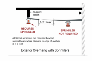
Courtesy: Roland ASP, CET NFSA Technotes.