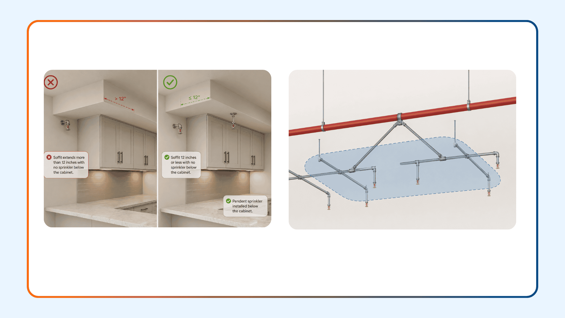
Description: The question concerns the sprinkler arrangement where there is a horizontal soffit more than 12 inches in length and the cabinets are fitted flush with the underside of the soffit. This pertains to whether or not a sidewall sprinkler installation is acceptable without a pendent sprinkler below the cabinet. The situation illustrates the relevance of soffit size, cabinet location, and sprinkler installation.
Question 1. Is a sidewall sprinkler legal in a soffit that extends horizontally more than 12 inches if the cabinets are flush with the soffit and there is no pendent sprinkler under the cabinet?
Ans. No, it wouldn’t be allowed to do that. NFPA 13 2022 edition, Section 10.3.5.1.4.2 states a maximum of 12 inches with no sprinkler below the cabinet. NFPA 13 doesn’t allow any deviations to this criterion.
Annexe A.10.3.5.1.4 describes the design aims and provides the rationale and testing for this regulation. This is based on a test series conducted by the National Fire Sprinkler Association with assistance from Tyco International (Valentine and Isman, Kitchen Cabinets and Residential Sprinklers, National Fire Sprinkler Association, November 2005) that included fire modelling, distribution tests and full scale fire testing.
The committee also does not expect to require sprinklers under kitchen cabinets up to 12 inches deep, it adds. It also provides recommendations regarding sidewall placement, stating that if pendent sprinklers are not used, a sidewall sprinkler on the opposite wall is the next best option, followed by a sidewall on a soffit flush with the face of the cabinet. Sprinklers mounted on the wall behind the cabinet face are discouraged because of possible obstructions.
Description: NFPA 14 permits standpipe pressures of up to 400 psi; however, Schedule 10 and Schedule 40 steel pipe are only listed to 300 psi.
Question 2. Is there any information on pipe type for these greater pressures?
Ans. This has been a problem that the fire protection industry has experienced for many years; NFPA 14 has allowed standpipe system pressure up to 400 psi for many editions, while the referenced requirements for Schedule 10 and Schedule 40 steel pipe have generally been associated with applications not exceeding 300 psi. To help dispel this doubt, the NFPA 14 Technical Committee clarified, at the First Draft Meeting for the 2027 edition of the standard, requirements for piping used in higher-pressure standpipe systems.
In the 2027 First Draft changes, the standard will specifically restrict Schedule 10 steel pipe to systems with working pressures not to exceed 300 psi. There are new criteria in Sections 7.2.3.1 and 7.2.4.1 that state that the nominal wall thickness of the pipe must be adequate to handle the maximum system working pressure for systems with over 300 psi. Also, Section 7.2.3.2 and Section 7.2.4.2 stipulate that steel pipe listed specifically for pressures beyond 300 psi shall be installed in accordance with its listing/ratings and the manufacturer’s installation instructions.
Therefore, the 2027 edition does not specify a particular pipe schedule, such as Schedule 80, for 300 to 400 psi systems. Instead, the designer must choose tubing that is strong enough to handle the maximum working pressure required. This change addresses the previous confusion by restricting the usage of Schedule 10 pipe to 300 psi and introducing explicit performance requirements for standpipe systems greater than 300 psi.
Description: A project was originally intended to be supplied by the city’s water system. However, the city’s water supply has worsened, and it is now regarded as unstable and volatile. A suction tank will now be used as the primary water source.
Question 3. Is it still necessary to connect the city water supply to the fire pump discharge piping as a bypass?
Ans. No, a bypass through the client’s own subterranean water network is not necessary. The applicable requirements specify just one automated water supply for the fire protection system(s). In this situation, the suction tank and fire pump provide the required automatic water supply.
Section 4.14.4 of NFPA 20, 2010 edition, addresses fire pumps with bypasses and mandates a bypass if the suction supply has sufficient pressure to be of material use to the fire protection system even when the pump is not in operation. In this configuration, the fire pump suction supply is an at-grade water storage tank. As a result, without the fire pump, the suction supply cannot deliver enough pressure to be useful, and a pump bypass is unnecessary.
If desired, the private water service can be linked and regarded as a second water supply, as long as each water supply has the necessary check valve and components. However, supplying a second water source is optional and not necessary.
Description: This question addresses the growing practice of placing sprinkler pipe seams at the top of the pipe. It aims to determine the justification for this need and whether it is based on some code provision, standard or engineering practice. The genesis and use of this seam location requirement for sprinkler system installations is addressed in this question.
Question 4. We are increasingly receiving requests from engineers for sprinkler pipe seams to be inserted at the top of the pipe. Do you know when and where this requirement originated?
Ans. Fire sprinkler pipe is made from rolls of flat steel that are approximately 21 feet long. The flat steel is then rolled into a circular form, and the long edges are welded together, usually with electric welding resistance, or EWR.
Welded portions, often known as seams, are not necessarily as smooth as the pipe’s inside surfaces. In certain circumstances, the welds are less thick than the steel pipe itself. This can leave a space for water to settle, particularly in dry-pipe and preaction systems. The presence of water in the air can promote corrosion and cause pinhole leaks along welded joints.
When the pipe is fitted with the welded seams on top, corrosion is significantly reduced since small amounts of water do not accumulate along the rougher seams. As a result, some engineers require that the seam be put up, and many contractors follow this technique when installing piping.
Description: According to Annex Section A.8.15.5.4 of the 2016 edition of NFPA 13, ASME A17.1 requires lift equipment shutdown prior to/upon lift sprinkler activation using fire alarm devices or a water flow switch.
Question 5. Is this requirement applicable to sprinklers at the bottom of lift pits where there is no lift equipment beneath them?
Ans. According to our knowledge, this rule does not apply if there is no equipment below the sprinkler in the pit.
This opinion is based on ASME A7.1 The Elevator Safety Code (2019 version) Section 2.8.3.3.2, which reads as follows:
…where elevator equipment is located or its enclosure is
configured such that application of water from sprinklers
could cause unsafe elevator operation, means shall be
provided to automatically disconnect the mainline
power supply to the affected elevator and any other
power supplies used to move the elevator upon or
prior to the application of water.”
This clause stipulates that where water could produce harmful conditions, a method of turning off the electricity is required when the sprinklers are activated. If there is no equipment below the pit sprinkler, there appears to be little risk of a hazardous lift operation.
Additionally, this section contains the following language:
(c) The activation of sprinklers outside of such locations
shall not disconnect the mainline elevator power
supply.
Again, this phrasing appears to support the idea that a lift stoppage is not necessary in the situation stated.
It should be noted, however, that the NFSA are not experts on the Lift Safety Code, and interpretations may differ.
Description: The question is how to determine the zone of influence in the installation of sway bracing in sprinkler systems. It considers whether the zone needs to be centrally placed between branchlines or whether other placement configurations can be acceptable. The question relates the position of the sway brace to the layout of the branchline and the area covered by the brace.
Question 6. Does the zone of influence for sway bracing have to be centred between branchlines?
Ans. No, the zone of influence is not required to be centred on the sway brace.
According to NFPA 13, 2019 edition, Section 18.5.9.6, the zone of impact for lateral braces includes all branch lines, drops, sprigs, and mains tributary to the brace, with the exception of branch lines with longitudinal bracing or those forbidden by Section 18.5.9.6.1. Section
A.18.5.9.6 explains that zones of influence do not have to be symmetrical in terms of brace spacing.
NFPA 13 intends that the chosen zone of influence represents the worst-case load scenario.
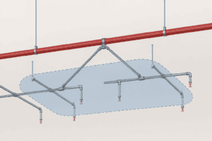
Description: A project contains branchlines with sprinklers of varying K-Factors. The local AHJ states that signs must be hung across the length of the structure between the two different k-factors.
Question 7. Is signage required between lines with varying k-factors and sprinkler thread sizes?
Ans. No, NFPA 13 does not need notice at the transition between sprinklers with varying K-factors on branch lines. Section 16.17 and its associated annex material specify the general criteria for signs, but do not require a sign when the sprinkler K-factor changes. The spare sprinkler cabinet information must identify the sprinklers installed in the building so that the appropriate replacements can be selected; however, this does not necessitate marking along branch lines. The different outlet and thread sizes also serve to keep the sprinklers from being accidentally interchanged. The International Fire Code (IFC) Chapter 32 does not appear to need this notice.
The AHJ shall identify and submit the appropriate adopted code, standard, or municipal regulation that supports the desired signage. Unless a locally enacted need exists, no signage is required.
Description: The 2025 edition of NFPA 20 says in Section 4.17.1.1 that “nonmetallic flexible pump connection fittings in the discharge piping shall not be permitted.”
Question 8. Does this clause imply that only metallic expansion joints are permitted on fire pump discharge piping?
Ans. Yes, the specification permits only metallic flexible pump connection connections in fire pump discharge piping.
Section 4.17.1 of NFPA 20, 2025 edition states that discharge components must include pipe, valves, and fittings that extend from the pump discharge flange to the system side of the discharge valve. Section 4.17.1.1 states that nonmetallic flexible pump connection connectors in discharge piping are not permitted.
Section 4.17.1.1 is new in the 2025 edition. This is from the First Revision No. 72. According to the committee statement, these fittings must be metallic since nonmetallic flexible pump connection connections are prone to failure.
Description: This question is about whether a lengthy arm-over in a sprinkler system is an offset or longer than 7 feet. It reviews the effects of these situations on the arm-over designation in the 2022 edition of NFPA 13. The question is specifically about the applicability of the requirements in Section 18.6.7.
Question 9. If an arm-over includes offsets or exceeds 7′-0″ in length, is it still defined as an arm-over that does not require line restraints per NFPA 13 Section 18.6.7 in the 2022 edition?
Ans. Yes, regardless of the length of the run, it is termed an arm-over if it only feeds one sprinkler.
It should be emphasised that caution should be exercised when there is a possibility that the sprinkler or pipe will be damaged by an earthquake or other building movement.
An arm-over is defined as: “A horizontal pipe that extends from the branch line to a single sprinkler or a sprinkler above and below a ceiling”.
Furthermore, the following is explanatory material linked with Section 18.6.7:
“Restraint provides additional support for branch lines. This is a clarification that restraint is not required for a drop or armover feeding a single sprinkler. However, if there is a single sprinkler drop that could be damaged from earthquake motion, especially from impact with other building or nonstructural components, restraint should be used.”
Description: Basement storage units are designated as R occupancy in an NFPA 13R building. The plans say, “311.1.1 A room or space used for storage purposes that is accessory to another occupancy shall be classified as part of that occupancy.”
Question 10. Can these be computed with the 13R 4-sprinkler approach, or do they require an NFPA 13 OH2 design?
Ans. Although the Building code may categorise this “basement storage area” as a R occupancy, the design standards are derived from NFPA 13R.
NFPA 13R primarily divides the criterion into two categories: inside dwelling units and outside dwelling units. Regardless of the Building Code classification, a basement storage facility is most likely deemed Outside the Dwelling facility.
6.2.2 Sprinklers outside the housing unit. (Often necessitating installation of quick response sprinklers.) A note of caution: section 6.2.2.2 lists the locations where residential sprinklers can be placed outside of the dwelling unit; however, a basement storage room is not one of these locations (unless it satisfies the criteria described in section 7.2.4.1). Therefore, quick response sprinklers are necessary per Section 6.2.2.1 and, as required in Section 6.3, spacing, obstruction criteria and distance below ceiling shall be in accordance with NFPA 13.
Design standards would be found in Section 7.2, named “Outside Dwelling Unit”.
Section 7.2.3 mandates that the discharge and design areas satisfy NFPA 13 regulations, unless the exceptions in Section 7.2.3.1 are met. This exception limits the design area to the number of rapid response sprinklers in the compartment but does not require more than four sprinklers. To use this exception, the storage container must be:
- Separated by 30-minute-rated construction.
- Sprinkler area: 130 square feet for Ordinary Hazard.
- Have 8-inch lintels
- Area of compartment openings cannot exceed 50 square feet.
- Discharge densities are consistent with NFPA 13.
Based on the foregoing, the design parameters for the basement storage area are computed using the standard NFPA 13 methodology (density/area or room design). Again, if the area fits the criteria outlined in Section 7.2.3.1, the design area could be limited to four quick response sprinklers.
Description: Section 8.16.1.2.1 A pressure-reducing valve shall be provided and configured to provide an outlet pressure of no more than 165 psi at the maximum inlet pressure.
Question 11. Could you define “maximum inlet pressure” in this context?
Is it appropriate to set the pressure-reducing valve to 165 psi and supply two floors below without exceeding 175 psi?
Ans. The requirement to limit the valve setting to 165 psi is designed to give a 10 psi safety factor up to the maximum system pressure of 175 psi.
According to NFPA 13, 2013 edition, Section 8.16.1.2.3, a relief valve of at least 1/2 inch size must be installed on the discharge side of the pressure-reducing valve and adjusted to operate at a pressure not exceeding the system’s rated pressure. This pressure relief valve, located on the discharge side of the pressure lowering valve, is designed to release surplus static pressure when there is no water flow.
No, setting the pressure-reducing valve to 165 psi and supplying two floors below is not permissible if the elevation shift increases the maximum system pressure on the lowest level to more than 175 psi. In this situation, the pressure lowering valve would need to be set to less than 165 psi to accommodate the additional pressure caused by the elevation change. The standard still demands that the maximum system working pressure not be exceeded.
Description: This question is concerning the hydraulic calculation requirements for two deluge systems separated by a draft curtain. The question is whether the draft curtain can be installed to NFPA 409 Section 6.7 and be hydraulically computed independently for each system. The question is how the separation of systems might alter the required approach to the calculation.
Question 12. If I construct a Draft Curtain as described in Section 6.7 to separate two systems, will I be able to hydraulically compute only one system at a time?
Ans. No, draft curtains erected according to Section 6.7 of NFPA 409, 2026 edition, will not allow you to compute only one system at a time.
There is nothing expressly mentioned in Section 6.7 of NFPA 409, 2026 edition, that would allow hydraulic calculation of one system at a time due to the presence of draft curtains.
Chapter 7, in particular Section 7.5.4.15, provides greater insight. Section 7.5.4.15 stipulates that the water supply must be capable of providing water to the greatest number of systems planned to operate. This section goes on to indicate that appropriate supply requirements are determined by assuming that a fire at any place will activate all of the systems in every draft curtain region that is entirely or partially within a 30 m (100 ft) horizontal radius of that point.
The way this section is written implies that the water supply must be able to support the operation of both systems if they are within a 100-foot radius.
Closing Thoughts
The questions in this edition demonstrate a common theme in fire prevention design: code compliance is rarely a matter of finding one governing sentence. Sound interpretation usually means cross referencing the main requirement to annexe material, to related portions of the same chapter, to committee statements from first revisions, and, in cases where the standard is silent or ambiguous, the underlying engineering rationale (e.g., the NFSA/Tyco cabinet sprinkler testing referenced in Item #1, or the corrosion mechanism behind seam orientation in Item #4). Designers that use only isolated section text risk both over-design and non-compliant under-design.
Several things in this series also speak to the significance of understanding of editions. The standpipe piping clarification for NFPA 14 (Item #2) and the deluge system calculation approach for NFPA 409 (Item #12) are from the 2027 and 2026 editions respectively, while the fire pump discharge connector restriction (Item #8) is new to the 2025 version of NFPA 20. The version selected by a jurisdiction may not follow the requirements set forth here or may be superseded in a subsequent cycle. Engineers and contractors should always check the applicable edition before treating any interpretation in this book as binding advise for a given project.
Finally, some responses (Items #3, #5, #7, #10, #11) are based on project-specific conditions—water supply characteristics, occupancy classification, equipment position, elevation changes—rather than a rule of fixed and general applicability. These responses should not be seen as a general answer, but as a framework for analysis. A substantially different combination of field conditions could vary the outcome.
Like previous editions of this series, this document will be updated when new code cycles are finalised and when new questions from the field come up. Readers whose project conditions do not closely match the scenarios mentioned here may submit their own technical questions for assessment and should consult directly with the AHJ or a licensed fire protection engineer before finalising system design.